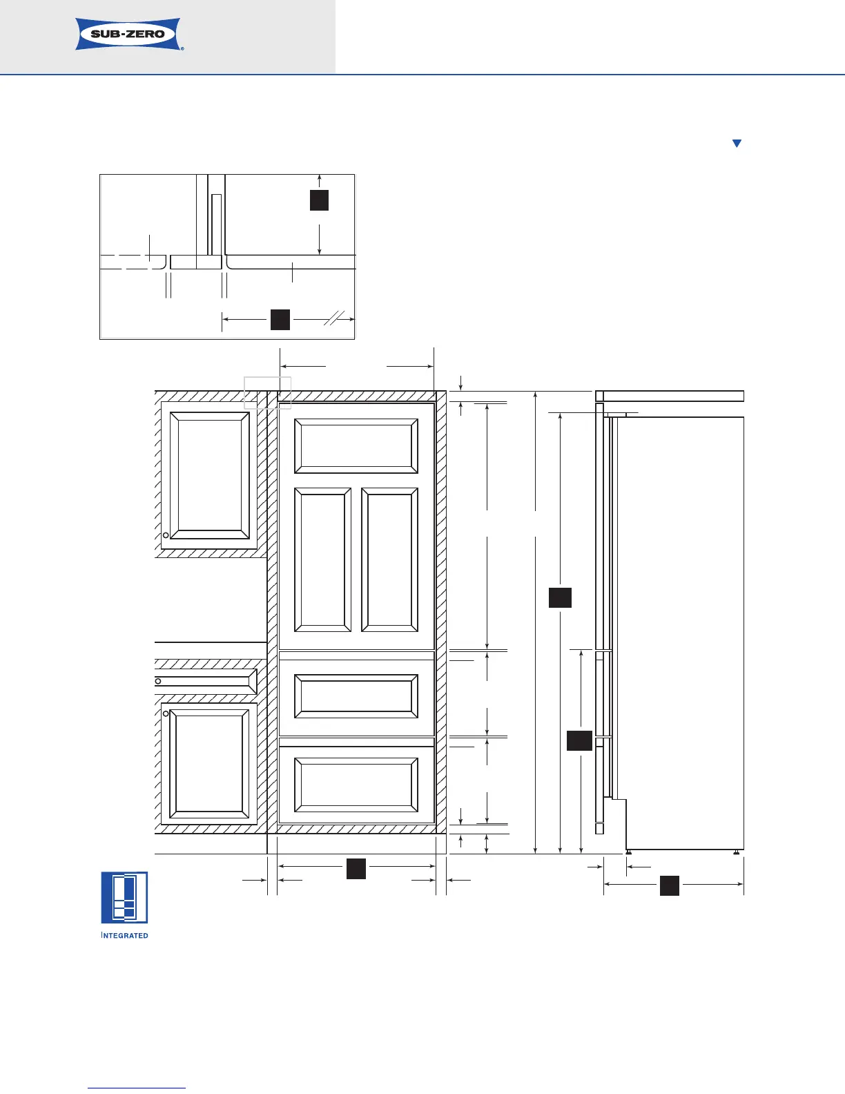
Planning Information
Model 700TC(I)
Dimensions in parentheses are in
millimeters unless otherwise specified.
8
A) ALL REVEALS ARE 1/8" (3)
B) DRAWER RAILS ARE ATTACHED TO DRAWER FRONTS
C) BOTTOM RAIL MUST BE REMOVABLE
*DIMENSIONS MAY VARY
C
A
A
A
B
B
TOP VIEW
A A
DOOR PA NEL
CABINET DOOR
TO WALL
SUB-ZERO
UNIT
PANEL WIDTH
1
1
/2"
(38)
1
1
/2"
(38)
47
7
/8"
(1216)
FRONT VIEW SIDE VIEW
2
6
3
/4" (679)
13
9
/16"
(345)
15
1
/16"
(383)
84"
(2624)
1
1
/2"
(38)
1
1
/2"
(38)
4"*
(102)
4" (102)
80"*
(2032)
34
1
/2"
(876)
*
24"
(610)
27"
(686)
SHADED AREA
INDICATES STATIONARY
STYLES AND RAILS
27"
(686)
2
4"
(610)
The illustration shows an Integrated tall unit installed
within a framed cabinetry beaded inset application.
IMPORTANT NOTE: Dimensions are based on a
1
/8" (3)
reveal. A reveal of up to
1
/4" (6) is possible, but panel
dimensions need to be adjusted accordingly.
FRAMED CABINETRY – BEADED INSET APPLICATION
Installation of an Integrated tall unit within
framed cabinetry.
*Dimensions ma
y v
ary.