Integrated Installation 12
Position the Unit
I
f two integrated units are installed closer than 2" (51) to
one another, refer to dual installations on page 20.
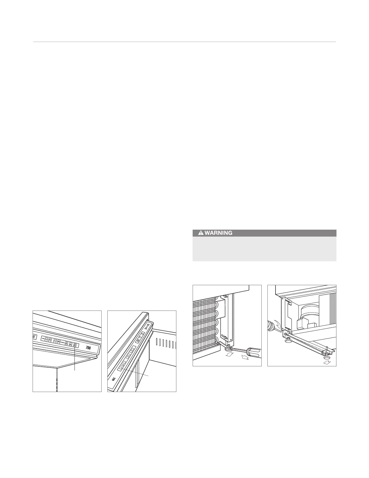
Plug the power cord into the electrical outlet. With power
applied to the unit, check for lighting and cooling. Press
the UNIT ON/OFF key pad on the control panel (POWER
for column models). Refer to the illustrations below. Once
you are satisfied that the unit is operating properly, shut
off power to the electrical outlet at the circuit breaker and
proceed.
Pre-level the unit before moving into position. This is to
allow the unit to engage the anti-tip bracket properly.
Slide the unit into position, making sure the anti-tip
bracket is engaged properly. Extend the front leveling legs
down approximately
3
/16" (5) to make additional adjust-
ments easier.
When the integrated unit is installed, the anti-tip bracket
will be positioned just below the engaging bracket on the
unit. It is not necessary to raise the unit up so that it locks
into the anti-tip bracket, but the unit must be in alignment
with the anti-tip bracket.
The floor under the integrated unit must be at the same
level as the surrounding finished floor to allow the com-
pressor tray to be slid forward for service.
On/off key pad—tall model. On/off key pad—drawer model.
C
O
L
D
ER
W
A
R
MER
R
EFRI
G
ER
A
T
O
R
FR
EEZ
ER
CO
LD
ER
W
AR
M
ER
I
C
E
ON
/O
FF
O
N
/O
FF
U
N
I
T
O
N
/O
FF
UNIT
ON/OFF
Level the Unit
L
evel the integrated unit by turning the front leveling legs
clockwise to raise or counterclockwise to lower the unit.
To assist you in adjusting the front leveling legs up or
down, use a standard screwdriver blade and place it in the
front leveling leg as shown in the illustration below.
The rear leveling legs are adjusted from the front of the
base by turning the Phillips head screw as shown in the
illustration below.
IMPORTANT NOTE: The rear leveling legs will only move
1
/16" (2) for every 18 revolutions on the Phillips head
screw. Do not over torque. Use the lowest torque setting
on any power screwdriver. Do not turn the rear leveling
legs by hand.
Once the unit is leveled, secure the unit in place by using
the side mounting clips and #8 x
1
/2" screws provided.
Front leveling legs. Rear leveling legs.
To reduce the possibility of the unit tipping forward,
the front leveling legs must be in contact with the floor.