Do you have a question about the Sub-Zero 736TC-3 and is the answer not in the manual?
Details product safety labels, signal words (WARNING, CAUTION, NOTE) and precautions.
Provides contact details for Sub-Zero Freezer Company for service and parts inquiries.
Illustrates the basic 700 Series electronic control system diagram.
Explains basic operations like ON/OFF, temperature adjustment, and icemaker control.
Details how to adjust temperature set-points using WARMER or COLDER keys.
Explains how thermistors signal the microprocessor to regulate compartment temperatures.
Explains how excessive compressor run time triggers 'SERVICE' and error codes.
Illustrates common error indicators customers may see on the LCD display.
Explains how to initiate Diagnostic Mode, Manual Component Activation, and Temp Log Recall.
Allows observation of real-time thermistor readings and error codes.
Lists error codes, their indications, and associated problems.
Details the procedure to clear registered error codes after problem correction.
Provides general rules and procedures for servicing 700-3 Series sealed systems with 134a.
Outlines best practices for working with 134a refrigerant, including equipment and procedures.
Details service procedures for common sealed system problems like leaks and restrictions.
Provides step-by-step voltage and continuity tests for diagnosing modular icemaker faults.
Provides systematic procedures for testing icemaker faults and identifying defective components.
Details the procedure for accessing and removing the control board.
Covers accessing and removing core sealed system components.
Provides steps for removing the high-side filter-drier attached to the unit tray.
Details the procedure for removing the compressor, including disconnecting tubing and electricals.
Explains how to remove the condenser secured to the unit tray by rivets.
Explains how to use error codes to diagnose and troubleshoot system issues.
Lists error codes, their indications, and associated problems.
Provides detailed troubleshooting steps for each error code identified.
Guides users on matching unit problems with possible causes and test actions.
Addresses causes and solutions for warm freezer temperatures accompanied by 'SERVICE' flashing.
Addresses causes and solutions for warm freezer temperatures without 'SERVICE' flashing.
Addresses causes and solutions for warm refrigerator temperatures with 'SERVICE' flashing.
Addresses causes and solutions for warm refrigerator temperatures without 'SERVICE' flashing.
Provides tables for diagnosing sealed system issues based on pressures and temperatures.
Explains how pressure readings indicate possible mechanical or sealed system problems.
Correlates evaporator temperatures with sealed system low-side pressures for diagnostics.
Provides continuity test procedures for the control panel membrane switch and ribbon cable.
Details testing and correcting door closing problems related to hinge operation.
Presents the wiring diagram for the 700TC-3 model.
Presents the wiring schematic for the 700TC-3 model.
Presents the wiring diagram for the 700TR-3 model.
Presents the wiring schematic for the 700TR-3 model.
Presents the wiring diagram for the 700TF/I-3 model.
Presents the wiring schematic for the 700TF/I-3 model.
Presents the wiring diagram for the 736TC/I-3 model.
Presents the wiring schematic for the 736TC/I-3 model.
Presents the wiring diagram for the 736TR-3 model.
Presents the wiring schematic for the 736TR-3 model.
| Width | 36 inches |
|---|---|
| Cooling System | Dual refrigeration |
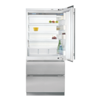
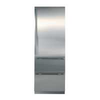
| Finish | Stainless Steel |
| Ice Maker | Yes |
| Product Type | Built-In Refrigerator |
| Door Style | French Door |
| Height | 84 inches |
| Depth | 24 inches |