Integrated
Integrated
(700-
(700-
3
3
T
T
ALL)
ALL)
Series
Series
Component Access/Removal
7-13
#3758412 - Revision B - December, 2006
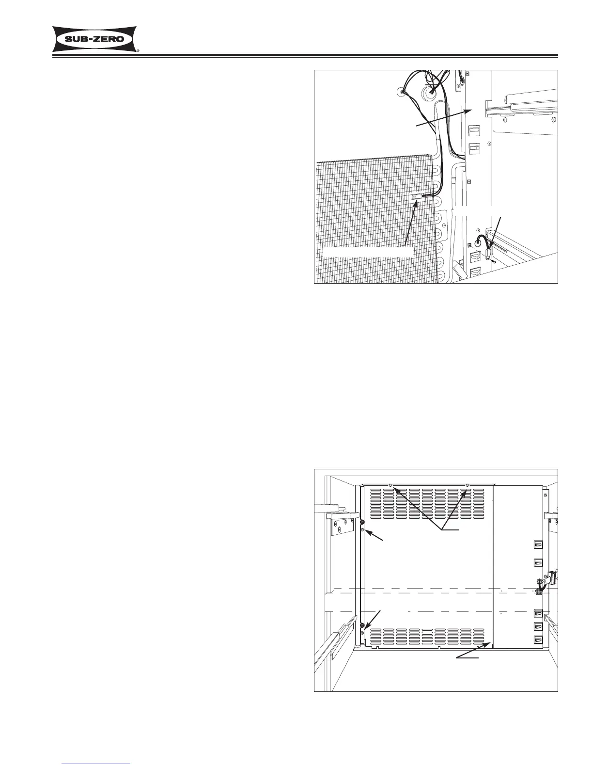
Lower Compartment Thermistor Removal
(Models 700TR-3 & 736TR-3)
The lower compartment thermistor in these models is
attached at front of the switch enclosure with a screw.
To access and remove the lower compartment thermis-
tor, first remove drawers, left side drawer slides, heat
exchanger cover and lower evaporator cover, then (See
Figure 7-27):
1. The screw securing compartment thermistor to
switch enclosure will be removed when evaporator
cover is removed.
2. Extract switch enclosure mounting screws and pull
enclosure away from back wall.
3. Cut thermistor’s wire leads six (6) to twelve (12)
inches from back wall.
Lower Evaporator Thermistor Removal
(Models 700TR-3 & 736TR-3)
The lower evaporator thermistor in these models is
inserted into the third opening in the evaporator fins
from the top, approximately to the center of the evapo-
rator.
To access and remove the lower evaporator thermistor,
first remove drawers, left side drawer slides, heat
exchanger cover and lower evaporator cover assembly,
then (See Figure 7-27):
1. Cut thermistor’s wire leads six (6) to twelve (12)
inches from the back wall.
2. Pull thermistor from evaporator fins.
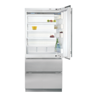
Lower Evaporator Cover Assembly Removal
(Models 700TC/I-3, 700TF/I-3, 736TC/I-3)
The lower evaporator cover in these models is held in
place with screws and a locating peg. The left side
mounting screws are hidden by the heat-exchanger
cover; screws at top secure evaporator cover to ceiling
of lower compartment; a peg protruding from the bot-
tom left side of switch enclosure fits into a hole at bot-
tom right side of evaporator cover.
To access and remove the lower evaporator cover, first
remove drawers, left side drawer slides, and heat
exchanger cover, as well as icemaker, if applicable,
then (See Figure 7-28):
1. Extract left side and top mounting screws.
2. Pull evaporator cover toward left wall to disengage
peg from hole at bottom right, then pull assembly
out through upper drawer opening.
Figure 7-28. Evaporator Cover Removal,
Model 736TC/I-3 Shown
Evaporator Cover
Screw
Screws
Screw
Peg
(Not Shown)
Figure 7-27. Lower Thermistors, 700TR-3
Evaporator Thermistor
Compartment Thermistor
Switch Enclosure