140cc. or 4-3/4oz. Fill
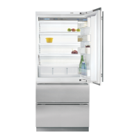
Figure 6-1. Modular Icemaker Electrical Schematic
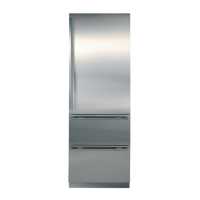
What Happens During Modular Icemaker Ejector Blade Rotation (700TFI-3 ONLY)
Figure 6-2 represents a view of the ejector blade from the front (or module side) of the icemaker. This diagram indi-
cates what happens during the rotation of the ejector blade and will assist the Service Technician in diagnosing ice-
maker problems.
Figure 6-2. Ejector Blade Rotation Diagram
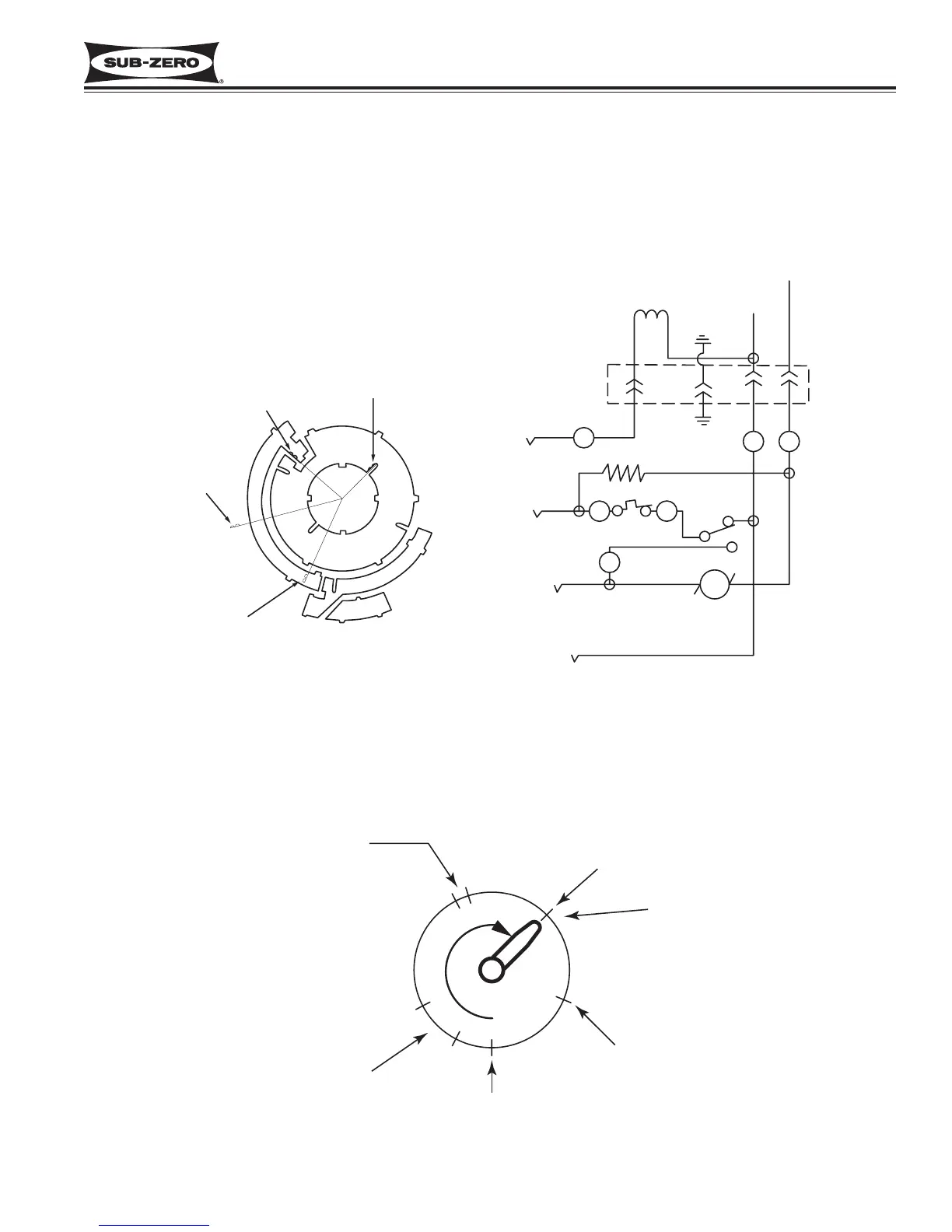
MODULAR ICEMAKER OPERATION (700TFI-3 ONLY)
When the icemaker thermostat has sensed temperatures of 17°F, the thermostat closes. At this time, the current
now has a path through the thermostat to the motor. The motor is linked with the drive gear. From the module,
there are copper contacts that ride on copper strips on the backside of the drive gear. (See Figure 6-1) As the drive
gear rotates, these contacts from the module will make or break a circuit (track) to the copper strips to generate the
icemaker cycle.