Integrated
Integrated
(700-
(700-
3
3
T
T
ALL)
ALL)
Series
Series
Electronic Control System
3-15
#3758412 - Revision B - December, 2006
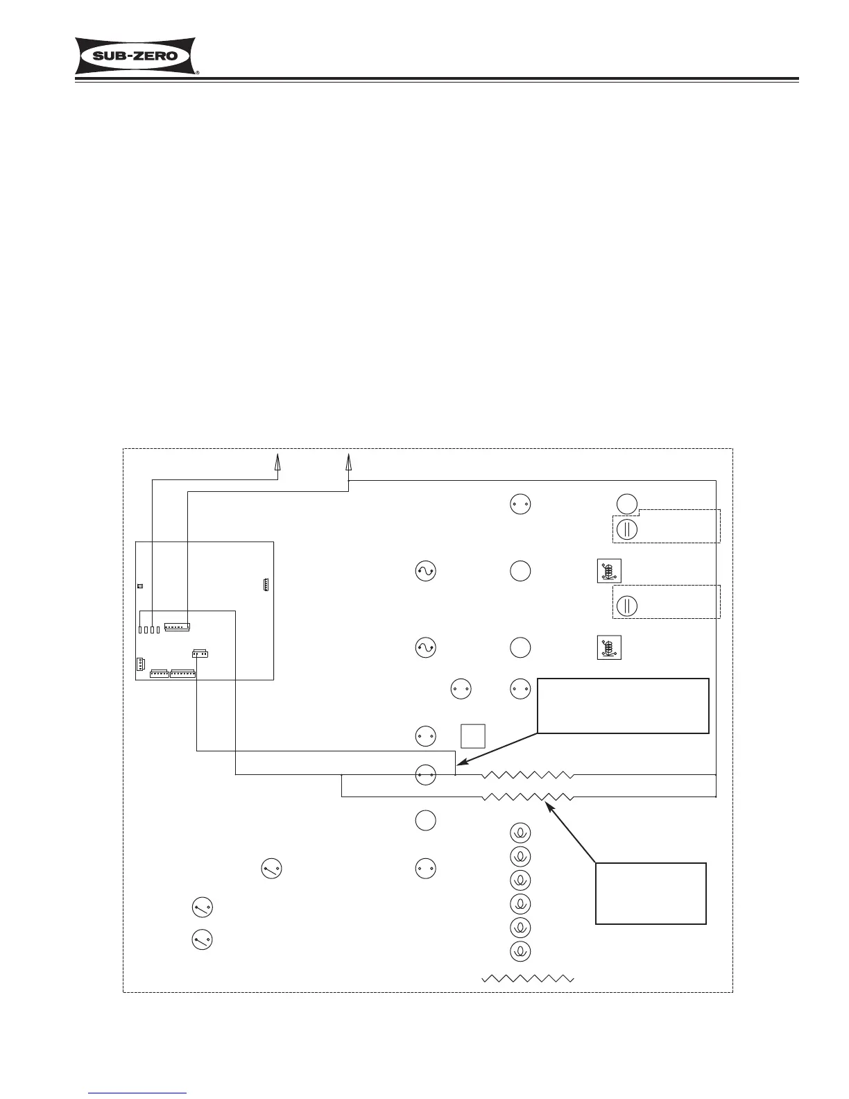
Monitor and Control Freezer “Adaptive Defrost”
Initially the freezer compressor will cycle-run for twelve hours (twenty-four hours in the model 700TF/I-3), after which
the microprocessor sends the signal to the defrost relay on the control board to close. This supplies power to the
defrost heater, and the compressor is switched off (See Figure 3-24). With the “Adaptive Defrost” technique, the
length of time that the heater actually stays on to defrost the evaporator and satisfy the defrost terminator is
observed by the microprocessor. The microprocessor then determines the number of hours before the next defrost.
If the heater stays on for a shorter time than specified, the microprocessor increases the next defrost interval. If the
heater stays on longer than specified, the electronic control decreases the next defrost interval. This is an ongoing
process whereby the defrost time and the defrost interval will vary by unit use.
NOTE: A five (5) minute time delay/dwell follows all defrosts, except in the model 700TF/I-3 where the delay/dwell is
ten (10) minutes. The drain trough heater is energized during defrost and the delay/dwell period.
NOTE: The minimum defrost interval is six (6) hours; The maximum defrost interval is eighty (80) hours; the maxi-
mum defrost duration is twenty-five (25) minutes.
NOTE: If the defrost sensing line is open, defrost operation defaults to 25 minute defrost time / 6 hour build time,
and Error Code 22 is logged. If the evaporator thermistor detects an under-heat or overheat situation at the same
time, Error Codes 20 or 23 is logged, respectively.
NOTE: During defrost, the displayed temperature is locked.
Figure 3-24. 700TC/I-3 Signal Trace Schematic (High Voltage) of Freezer Adaptive Defrost