Electronic Control System
Integrated
Integrated
(700-
(700-
3
3
T
T
ALL)
ALL)
Series
Series
3-16
#3758412 - Revision B - December, 2006
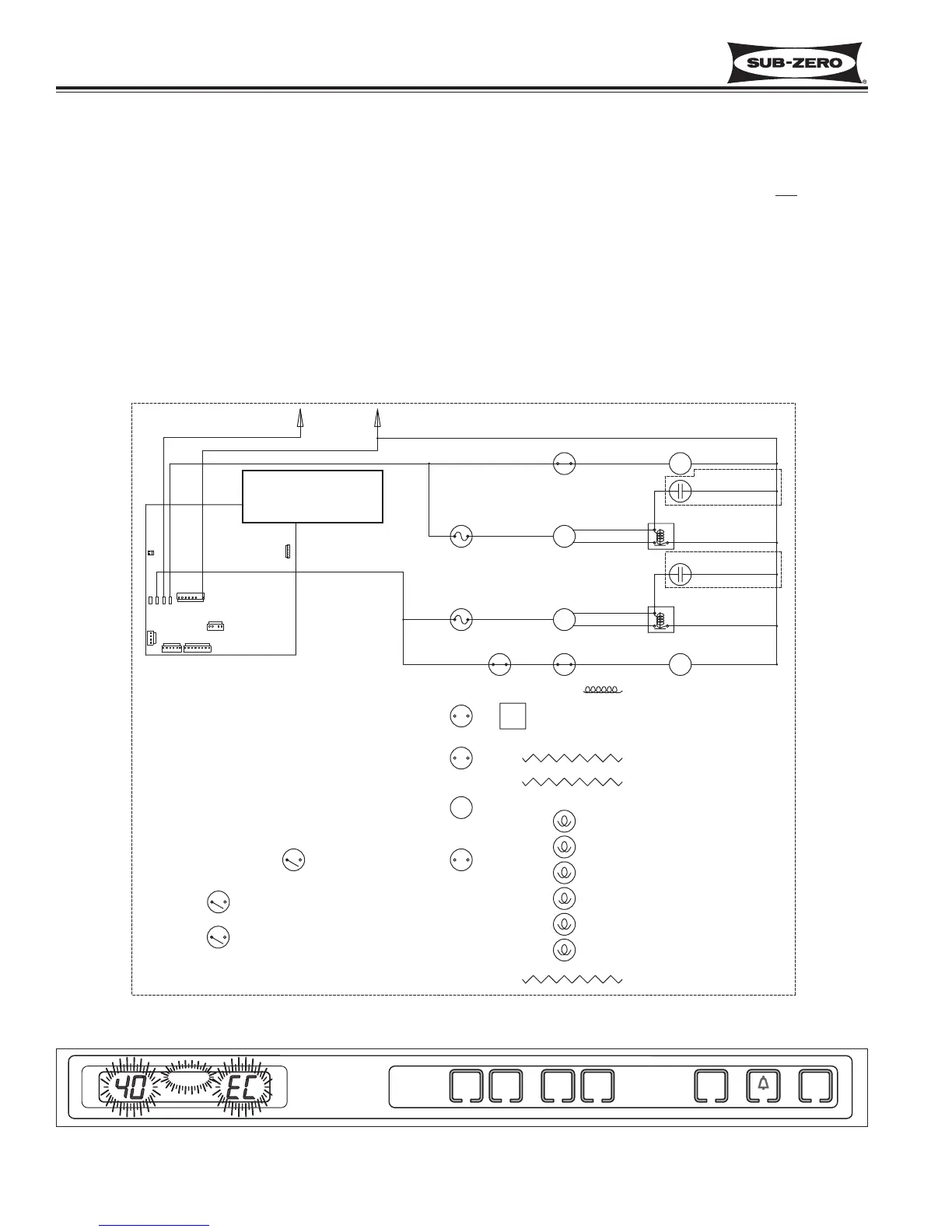
Figure 3-25. 700TC/I-3 Signal Trace Schematic (High Voltage) of Compressor Electrical System
Figure 3-26. “SERVICE”, “40” or “50” and “EC” Flashing = Several Excessive Compressor Run Periods
length of compressor
run time is monitored
by microprocessor.
Monitor Compressor Run Duration, Displays If Service is Needed
In all models except the 700TF/I-3, the microprocessor observes the changing state of the compressor relays to
determine the length of compressor run time (See Figure 3-25). If a compressor runs 100% (Fre = 6 hours / Ref = 4
hours), an error code is logged (EC 40 / EC 50, respectively), and defrost is initiated, but SERVICE will not flash.
If several 100% run periods occur, and the compartment temperature does not fall to at least the set point / low off-
set temperature average (and the door is not opened during the last run period), then SERVICE will flash along with
the error code (See Figure 3-26).
NOTE: To clear a flashing SERVICE and EC, the problem must be corrected, then switch the unit off then back on
and/or press the Bell ON/OFF key for 15 seconds. Failure to clear an error code will cause SERVICE to display
constant once Diagnostic Mode is initiated.
NOTE: If the unit is ever switched OFF then back ON, the compressor will not energize for at least 3 minutes. This
3 minute minimum OFF time is used to protect the compressor and its electricals.