Electronic Control System
Integrated
Integrated
(700-
(700-
3
3
T
T
ALL)
ALL)
Series
Series
3-22
#3758412 - Revision B - December, 2006
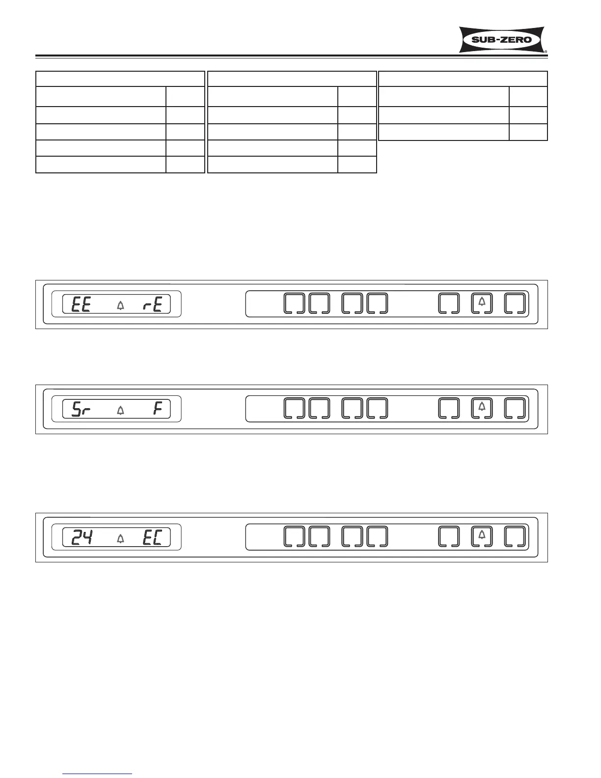
Figure 3-52. “EE” Observed in Diagnostic Mode = Thermistor Fault in Location Indicated by Code
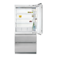
Figure 3-53. “Sr” Observed While in Diagnostic Mode = Unit is in Showroom Mode
Diagnostic Mode Indicators
If “EE” is observed in the left display area during Diagnostic Mode, the thermistor in that location is open or shorted,
or there is a break in that thermistor’s wiring (See Figure 3-52).
If “Sr” is observed in the left display area when Diagnostic Mode is initiated, the unit is in Showroom Mode, which
was explained earlier in this section (See Figure 3-53).
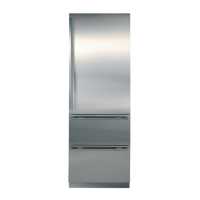
If “EC” is observed in the right display area during Diagnostic Mode, the numbers at left are “Error Codes” (See
Figure 3-55 and the Error Code Table on next page). Error Codes indicate problems registered by specific compo-
nents. If error codes are registered, they will appear before temperature readings and can be toggled through with
the temperature readings as described on the previous page.
Figure 3-55. “EC” Observed While in Diagnostic Mode = Error Code (See Table on Following Page)
700TC/I-3 & 736TC/I-3
THERMISTOR LOCATION CODE
Freezer Compartment F
Refrigerator Compartment r
Freezer Evaporator FE
Refrigerator Evaporator rE
700TR-3 & 736TR-3
THERMISTOR LOCATION CODE
Lower Compartment L
Upper Compartment U
Lower Evaporator LE
Upper Evaporator UE
700TF/I-3
THERMISTOR LOCATION CODE
Freezer Compartment F
Freezer Evaporator FE