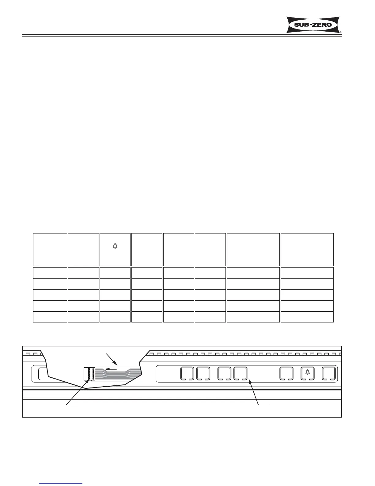
Exposed pins on back side of housing.
NOTE: See “How To Identify Pin 1”, above.
Ribbon Cable
Membrane Switch in
Control Panel Assembly
Figure 8-1. Control Panel Assy with Cut-Away View to Show Ribbon Cable (700TCI-3 Shown)
CONTROL PANEL MEMBRANE SWITCH / RIBBON CABLE TEST
If integrity of control panel assembly is suspect, perform continuity tests at membrane switch ribbon cable terminal
housing. Begin by disconnecting ribbon cable from control board. Disengage control board from control panel.
Remove control panel assembly from unit and place it on solid surface.
Pin 1 Identification Procedure
The ribbon cable wires are exposed at the back-side of the terminal housing. Pin 1 is labeled on the ribbon cable
(see Figure 8-1). If Pin 1 is not labeled and if:
1. Terminal housing is blue, then Pin 1 is indicated by the arrow on the housing.
2. Terminal housing is black, then place ohm meter leads between 1st and 2nd pin from each end of the housing
while pushing UNIT ON / OFF Key. When continuity is observed, pin 1 is at that end.
Continuity Test Procedure
1. Without pressing any of the keys on the membrane switch, check for continuity across all pin combinations. With
no keys pressed, there should be no continuity between any two pins.
2. Identify model number being serviced in left column of table below.
3. Press key listed at top of table.
4. Corresponding numbers to right of model number and below key being pressed are the pin numbers on terminal
housing that should have continuity.
NOTE: If any continuity tests show failure, replace entire control panel assembly.
ICE
ON/OFF
KEY
FREEZER
(RERIG LOWER)
COLDER
KEY
FREEZER
(RERIG LOWER)
WARMER
KEY
REFRIG
(UPPER)
COLDER
KEY
REFRIG
(UPPER)
WARMER
KEY
ALARM
( )
ON/OFF
KEY
UNIT
ON/OFF
KEY
MODEL
2 - 3 4 - 53 - 45 - 61 - 62 - 51 - 2700TC/-3
NA 4 - 53 - 45 - 61 - 62 - 51 - 2700TR-3
2 - 3 4 - 53 - 4NANA2 - 51 - 2700TFI-3
2 - 3 4 - 53 - 45 - 61 - 62 - 51 - 2736TCI-3
NA 4 - 53 - 45 - 61 - 62 - 51 - 2736TR-3