Component Access/Removal
Integrated
Integrated
(700-
(700-
3
3
T
T
ALL)
ALL)
Series
Series
7-14
#3758412 - Revision B - December, 2006
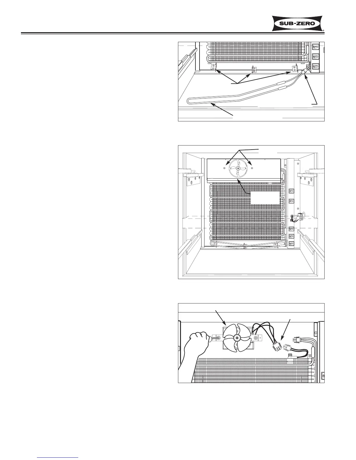
Drain Trough Heater Removal
(Models 700TC/I-3, 700TF/I-3, 736TC/I-3)
The drain trough heater in the lower compartment is
positioned just above the drain trough and held in place
by three heater brackets.
To access and remove the drain trough heater, first
remove drawers, left side drawer slides, heat exchanger
cover and the evaporator cover, then (See Figure 7-29):
1. Pull heater up and out of notches in the side brack-
ets, and down and out of notches in middle bracket.
2. Pull heater toward left until electrical connections
emerge from behind switch enclosure, then discon-
nect electrical leads.
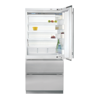
Lower Evaporator Fan Shroud Removal
(700TC/I-3, 700TF/I-3 & 736TC/I-3)
The lower evaporator fan shroud is attached to the
evaporator fan bracket assembly with two screws.
To access and remove the lower evaporator fan shroud,
first remove drawers, left side drawer slides, heat
exchanger cover and the evaporator cover. Then,
extract the screws that pass through the fan shroud into
the evaporator fan bracket. (See Figure 7-30)
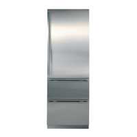
Lower Evaporator Fan Assembly Removal
(700TC/I-3, 700TF/I-3 & 736TC/I-3)
The lower evaporator fan assembly in these models is
attached to the upper back wall of the lower compart-
ment with screws.
To access and remove the lower evaporator fan assem-
bly, first remove drawers, left side drawer slides, heat
exchanger cover, evaporator cover and the evaporator
fan shroud, then (See Figure 7-31):
1. Disconnect fan wire leads from wire harness.
2. Extract fan assembly mounting screws from back
wall and pull fan assembly from unit.
NOTE: The evaporator fan blade is pressed onto
the shaft of the fan motor and can be removed by
simply pulling it away from the motor.