Component Access/Removal
Integrated
Integrated
(700-
(700-
3
3
T
T
ALL)
ALL)
Series
Series
7-18
#3758412 - Revision B - December, 2006
COMPRESSOR AREA ELECTRICAL AND MECHANI-
CAL COMPONENTS
Icemaker Water Valve Removal
(700TC/I-3, 700TF/I-3 & 736TC/I-3)
The icemaker water valve assembly is located at the
right side of the compressor area next to the condenser,
and is attached to the valve bracket with screws.
NOTE: Before accessing the icemaker water valve,
turn off water supply to the unit.
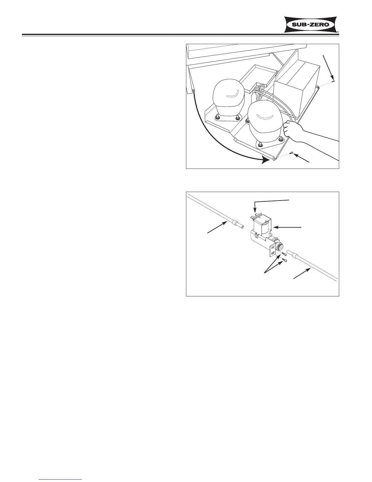
To remove the water valve, the kickplate/grill will need
to be removed first and the unit tray slid out. To slide
the unit tray out, extract the two screws that secure the
tray to the unit, located at the front right and left cor-
ners. Grab the front flange of the tray and pull forward.
(See Figure 7-39), then (See Figure 7-40):
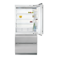
1. Disconnect inlet water tube from the valve inlet by
pushing collar around tube toward valve, while
pulling inlet water tube away from valve.
2. With a Phillips screwdriver, remove screws from
valve bracket.
3. Lower valve and pull forward.
4. Disconnect valve electrical leads.
5. Disconnect outlet tube from the valve outlet by
pushing collar around tube toward valve, while
pulling outlet water tube away from valve.
Figure 7-40. Water Valve Removal, TC/I-3,TF/I-3
Outlet Tube
Mounting Screws
Inlet Tube
Electrical Leads
Water Valve
Figure 7-39. Sliding Unit Tray Out
Screw
Screw