Integrated
Integrated
(700-
(700-
3
3
T
T
ALL)
ALL)
Series
Series
Electronic Control System
3-17
#3758412 - Revision B - December, 2006
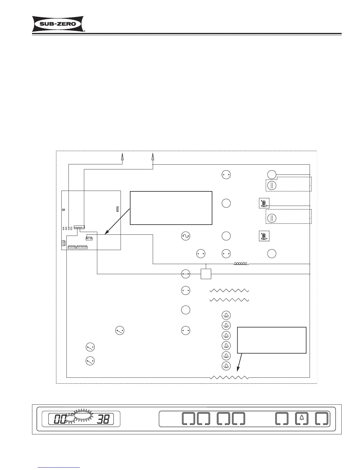
Figure 3-28. 700TC/I-3 Signal Trace Schematic (High Voltage) of Icemaker Electrical System
Figure 3-29. ICE & SERVICE Flashing = Solenoid Energized 15 sec., every 24 hrs., 5 consecutive times
115 Volts to water valve solenoid
is monitored by microprocessor.
If voltage supply lasts more than
15 seconds, power to icemaker
system is disabled.
Fill tube heater is energized
whenever icemaker system
is switched “ON” and ICE
appears on LCD
Monitor Icemaker System and Display If Service is Needed
The microprocessor observes the 115 Volts AC supplied to the icemaker water valve solenoid. If the solenoid is
energized for more than 15 seconds, power to the icemaker system is disabled for 24 hours (See Figure 3-28), and
an error code is logged (EC 30). If this happens five consecutive times, ICE and SERVICE on the LCD will flash
(See Figure 3-29), and the ICE ON/OFF key will be disabled.
NOTE: To clear the ICE and SERVICE error indicators, and reactivate the ICE ON/OFF key, the problem must be
corrected, then the unit must be switched OFF and back ON, and the Alarm key must be pressed for 15 seconds to
clear the Error Code.
NOTE: To allow ice to freeze fully and reduce effects of low water pressure, power to the icemaker system is inter-
rupted for 45 minutes after each ice harvest. This can be bypassed for service purposes by switching the icemaker
system OFF, then back ON using the ICE ON/OFF key.
NOTE: When in Sabbath Mode, the icemaker system is disabled. Sabbath Mode will be covered later.