Electronic Control System
Integrated
Integrated
(700-
(700-
3
3
T
T
ALL)
ALL)
Series
Series
3-12
#3758412 - Revision B - December, 2006
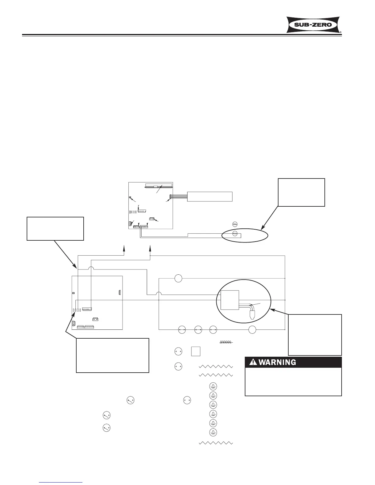
Assist in Control of Variable Speed Compressors (700TF/I-3 Only)
As mentioned on the previous page, temperature signals from the thermistors in the compartment are monitored by
the microprocessor and then displayed on the LCD.
When the compartment reaches high-offset (calling for cooling), an “ON” signal is sent from the control board to the
compressor’s inverter. The inverter (which is supplied with AC power at all times) then provide high DC voltage (3-
phase, 50 - 150 Hz), outputs to the compressor. The inverter in turn senses the compressor load. If the compressor
load is high, the speed command from the inverter will be for high speed compressor operation; if medium compres-
sor load, speed command from the inverter will be for medium speed; if low compressor load, speed command from
the inverter will be for low speed. If/when the compartment reaches low-offset, an “OFF” signal is sent to the invert-
er, which then cuts DC power to the compressor.
NOTE:
• The variable speed compressor, evaporator fan and the condenser fan will run a great majority of the time. This is
normal. These components will only cycle off during defrost and may also cycle off for short periods of time if the
ambient temperature is low enough.
• Initial speed command from an inverter to a compressor are always for High speed.
LT. BLUE
Figure 3-21. 700TF/I-3 Signal Trace Schematic of Variable Speed Compressor Operation
IN EXCESS OF 200 VOLTS MAY
BE PRESENT AT INVERTER
AND COMPRESSOR!
1. Compartment
temperature
monitored by
microprocessor
3. Inverter supplies
high DC voltage,
3-phase, 50 - 150
Hz signal, based
on compressor
load.
2. When cooling is called for,
115 Volts AC “ON” signal
supplied to compressor
inverter, evaporator fan
and condenser fan.
NOTE: Line voltage
supplied to inverter
at all times.