6
|
English subzero.com
|
7
SITE PREPARATION
CONCRETE WEDGE ANCHOR INSTALLATION:
1 Drill a 10 mm diameter hole any depth exceeding the
minimum embedment. Clean the hole or drill additional
depth to accommodate drill nes.
2 Assemble the washer and nut ush with the end of
anchor to protect threads. Drive the anchor through the
material to be fastened until the washer is ush with the
surface material.
3 Expand the anchor by tightening the nut 3–5 turns past
hand-tight position or to 34 newton-meters of torque.
WARNING
Verify there are no electrical wires or plumbing in the
area which the screws could penetrate.
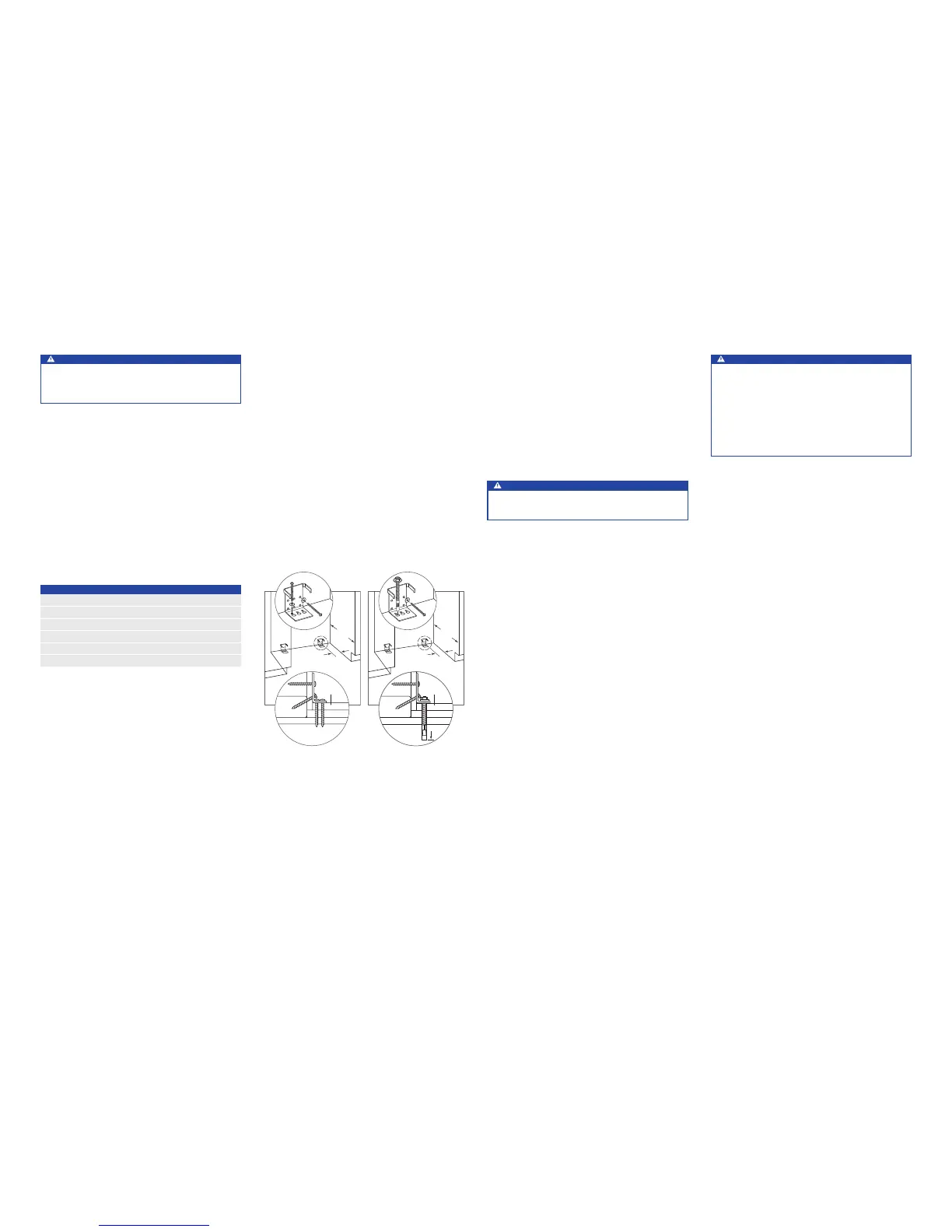
WOOD FLOOR APPLICATION
After properly locating the anti-tip brackets in the opening,
drill pilot holes 5 mm diameter maximum in the wall studs or
wall plate. Use the #12 screws and washers to secure the
brackets. Verify the screws penetrate through the ooring
material and into wall studs or wall plate a minimum of 19
mm. Refer to the illustration below.
CONCRETE FLOOR APPLICATION
After properly locating the anti-tip brackets in the opening,
drill pilot holes 5 mm diameter maximum in the wall studs
or wall plate. Drill 10 mm diameter holes into the concrete a
minimum of 38 mm deep. Use the #12 screws and washers
to secure the brackets to the wall, and use the
3
/8" wedge
anchors to secure the brackets to the oor. Verify the screws
penetrate wall studs or wall plate a minimum of 19 mm.
Refer to the illustration below.
102 mm
MIN
610
mm
SUBFLOORING
WOOD FLOOR
WALL PLATE
FINISHED
FLOORING
102 mm
MIN
610
mm
SUBFLOORING
CONCRETE
FLOOR
WALL PLATE
FINISHED
FLOORING
1
1
/
2
"
(38)
min
SUBFLOORING
CONCRETE
FLOOR
WALL PLATE
FINISHED
FLOORING
38 mm
MIN
Wood floor.
Concrete floor.
Anti-Tip Bracket
WARNING
To prevent the unit from tipping forward and provide
a stable installation, the unit must be secured in place
with the anti-tip brackets.
The two anti-tip brackets must be installed exactly 610 mm
from the front of the opening to the back of the brackets
and a minimum of 102 mm from the sides of the opening.
This depth will increase to 665 mm for a ush inset installa-
tion based on 19 mm thick panels. Failure to properly posi-
tion the anti-tip brackets will prevent proper engagement.
Use all anti-tip bracket hardware as instructed for wood or
concrete oors.
IMPORTANT NOTE: For wood or concrete oor applications,
if the #12 screws do not hit a wall stud or wall plate, use the
#8 screws and #12 washers with the wall anchors.
IMPORTANT NOTE: In some installations the subooring or
nished oor may necessitate angling the screws used to
fasten the anti-tip brackets to the back wall.
ANTI-TIP HARDWARE
2 Anti-tip brackets
12 #12 x 64 mm pan head screws
4
3
/8"–16 x 95 mm wedge anchors
12 #12 at washers
4 #8–18 x 32 mm truss head screws
4 Nylon Zip-it
®
wall anchors
CAUTION
Always wear safety glasses and use other neces-
sary protective devices or apparel when installing or
working with anchors.
Anchors are not recommended for use in lightweight
masonry material such as block or brick, or for use in
new concrete which has not had sufficient time to cure.
The use of core drills is not recommended to drill holes
for the anchors.