subzero.com
|
7
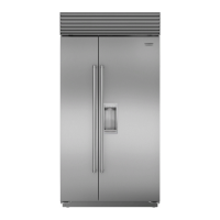
EXTERNAL DISPENSER
For external dispenser models, the dispenser glasswell will
need to be removed before custom panels can be installed.
IMPORTANT NOTE: The total panel thickness (including
backer and spacer, if used) in the glasswell area can range
from 6 mm to a maximum 29 mm. If the panel is thicker, the
area must be routed to 29 mm maximum thickness.
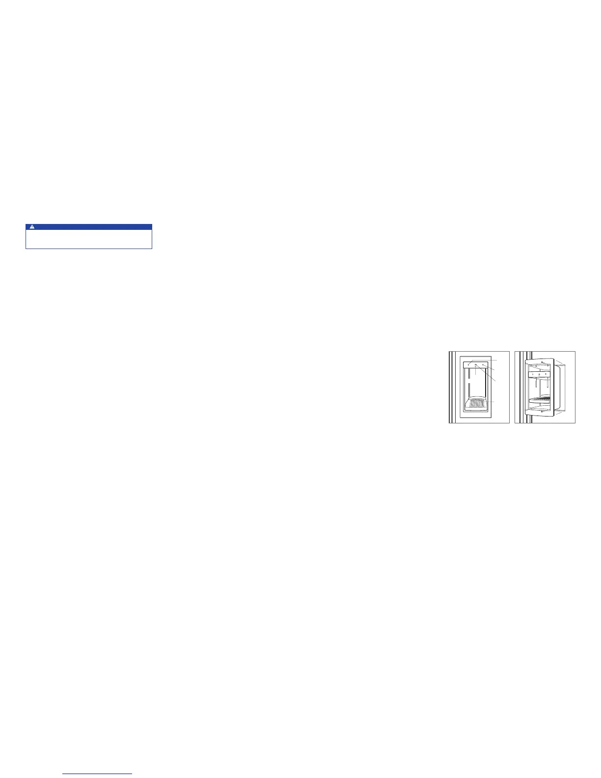
To remove the glasswell, lift the water grille up and out.
Remove the control panel by removing the center plastic
mandrel supports. Tilt the control panel out and disconnect
the wire harness (blue side up) from the back side. Remove
the bezel by removing the four screws. Refer to the illustra-
tions below.
Once custom panels have been installed, reverse the proce-
dure to reinstall the glasswell.
PANEL INSTALLATIONINSTALLATION
Water Line
Approximately .9 m of
1
/4" plastic tubing is connected to
the unit with a preassembled
1
/4" compression connection
under the unit. The water line tting connection kit, provided
with the unit, contains a
1
/4" compression union tting for
connection to the household water line.
Purge the water line prior to nal connection to the unit. This
will remove any debris that may be present in the tubing
from installing the new water line.
Place the sleeve and nut on the water line and fasten
to the connection at the end of the tubing. Do not over
tighten. Check all water line ttings for leaks. Verify the
drain pan can be installed and removed without water line
interference.
IMPORTANT NOTE: If a reverse osmosis system used, it is
recommended that the water ltration system be bypassed
by removing the lter.
IMPORTANT NOTE: Water lines can not be exposed to
freezing temperatures.
Custom Panels
For overlay and ush inset applications, custom door and
grille panels must be installed. Panel size is critical for a
proper t. To verify panel requirements and dimensions,
refer to the Sub-Zero design guide at subzero.com/specs.
IMPORTANT NOTE: Flush inset applications require a
minimum 13 mm reveal on all sides.
Finish all sides of custom panels. They may be visible when
the door is open.
ICE
WATER
LIGHT
WATER
GRILLE
LOCK
INDICATOR
Dispenser glasswell.
Glasswell removal.
Placement
CAUTION
Before moving the unit into position, secure door(s)
closed and protect any finished flooring.
Use an appliance dolly to move the unit near the opening.
If the unit has been on its back or side, it must stand upright
for a minimum of 24 hours before connecting power.
Plug the power cord into the grounded outlet and roll the
unit into position. Verify the anti-tip brackets are properly
engaged.
IMPORTANT NOTE: If used, side panels will need to be
installed before the unit is placed in its nal position. Refer
to page 8.