21
Controller :Controller should be installed in a place
protected by vibration, water and corrosive gasses and
where ambient temperature does not exceed the
values specified in the technical data.
Installation : Fixing and dimensions of panel models:
To fix the unit, slide the fastener 1 through the guides 2
as per the position shown in the figure. Move the fastener in
the direction of the arrow, pressing tab 3 it permits to move
the fastener in the opposite direction of the arrow. Once the
controller has been connected, they should be covered with
the lid 4 Silicon sealant should be applied along the
perimeter of the panel cut out or a rubber ‘O’ ring supplied
before the unit is fitted to increase protection against water
seepage.
Probe :To give a correct reading, the probe must be
installed in a place protected from thermal influences,
which may affect the temperature to be controlled.
22
CAUTION
WIRING: The probe and its corresponding wires should never
be installed in a conduit next to control or power supply lines.
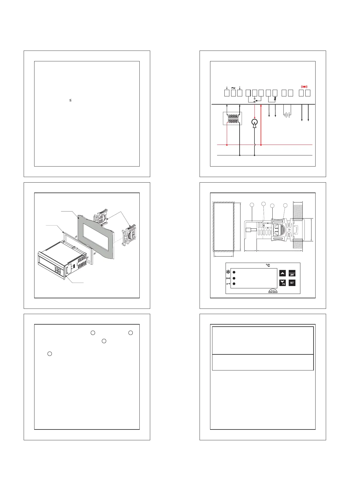
The electrical wiring should be done as shown in the diagram.
The power supply circuit should be connected to a protection
switch. The terminals admit wires of upto 2.5sq mm.
Notice: The information in this document is subject to
change in order to improve reliability , design or function
without prior notice and does not represent a commitment
on the part of the company. In no event will the company
be liable for direct, indirect, special, incidental or
consequential damage arising out of the use or inability to
use the product or documentation, even if advised of the
possibility of such damages. No part of this manual may
be reproduced or transmitted in any form or by any means
without the prior written permission of the company.
is done by qualified personnel only.
WARNING: Improper wiring may cause irreparable damage
and personal injury. Kindly ensure that wiring
Maintenance: Cleaning: Clean the surface of the controller
with a soft moist cloth. Do not use abrasive detergents, petrol,
alcohol or solvents.
20
SZ-7516-P
RST
88
-
3
1
4
2
34.5mm
71mm
19mm
10mm
MAX
71mm
29mm
Panel cutout
19
GASKET
PANEL
Side Lock
CONTROLLER
SuggestedWiringDiagram
10V
NEUTRAL
7
BUZZER
8
+ -
12
11
To SZ-N75
To SZ-B75
(10Vdc,
10mA max)
PHASE
3
1
Caution:Wiring for 230Vac load only
4
6
RELAY
NO C
NC
Compressor, Contactor
8(3)A max
5
9 10
BLACK
RED
+
-
BATTERY
INPUT
PROBE
9.6Vdc
18
17
Other on request
Housing : Black, ABS Plastic
Front Cover : Polycarbonate plastic.
Power input : 230Vac +/-20%,50-60Hz.
Technical data:
Frontal protection : I.P65
Panel Cutout : 29 X 71 mm
2.5sqmm one wire/ terminal only
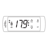
Display : 2 X14.2 mm (0.56") LED
Connections : Screw terminal blocks.
Data storage : Non-volatile EEPROM memory
Dimensions : Front : 75 X 34.5 MM,
Depth
:
7
1
MM (w/o back lid)
O O
Storage temp : -20 C to 70 C(non-condensing).
O
Accuracy : +/- 1 C.
Mounting : Flush panel mounting with fasteners
O O
Range : -50 C to 99 C.
Output :1 SPDT relay 8 (3)A, 250Vac.
O O
Operating temp.: 5 C to 50 C(non-condensing).
O O
Probe tolerance at 25 C : +/- 0.3 C.
Input : NTC probe, SZ-N75.
Battery Input For Backup : 9.6Vdc, 1800mAh (MAX)
on request for 72Hr Backup.
O
Resolution : 1 C.
Alarm (buzzer) : SZ-B75. 10Vdc,10mA.
 Loading...