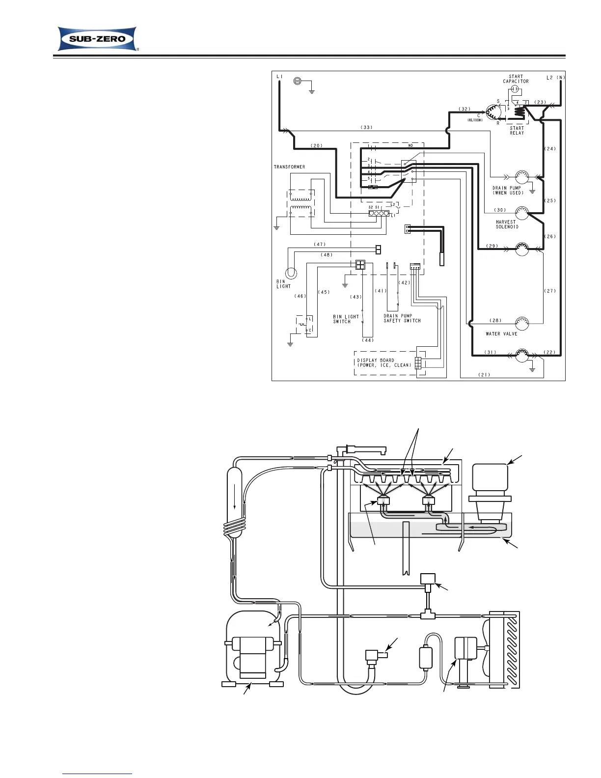
Freeze (Ice Making) Cycle
During the freeze cycle, only the compres-
sor, condenser fan motor and water pump
are energized (See Figure 3-7). The com-
pressor pushes refrigerant through the
sealed system, the condenser fan draws air
through the condenser, and the circulating
pump pushed water through the spray noz-
zles to the cube molds (See Figure 3-8).
The refrigerant running through the evapo-
rator absorbs heat from the water being
sprayed into the cube molds and the water
freezes. The heat that the refrigerant
absorbs from the water is carried in the
refrigerant back to the compressor and then
through the condenser where the heat is
transferred from the refrigerant to the air
being drown through the condenser by the
condenser fan. This warm air discharges
out through the left side of the kickplate.
As the freeze cycle runs, the electronic con-
trol monitors the temperature detected by
the thermistor attached to the liquid
line/condenser outlet (See Figure 3-7) and
calculates freeze time based on the the
amount of sub-cooling detected.
NOTE: Maximum freeze
cycle is 120 minutes.
NOTE: The Water System
During Freeze Cycle - The
reservoir is initially filled with
approximately two quarts of
water, either following a har-
vest cycle or after an initial
start-up. During the ice mak-
ing cycle, water is taken from
the reservoir and sprayed up
into the molds where it
freezes. However, water
containing mineral impurities
requires lower temperatures
to freeze, so the less pure
water falls back into the
reservoir while the purer
water freezes in the cube
molds. This causes the
water in the reservoir to
become highly concentrated
with mineral impurities at the
end of the freeze cycle.
Figure 3-8. Refrigeration and Water System Diagram - Freeze (Ice Making) Cycle