Electronic Control System
Under Counter (UC-24) Series
3-3
#7003933 - Revision B - November, 2007
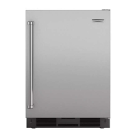
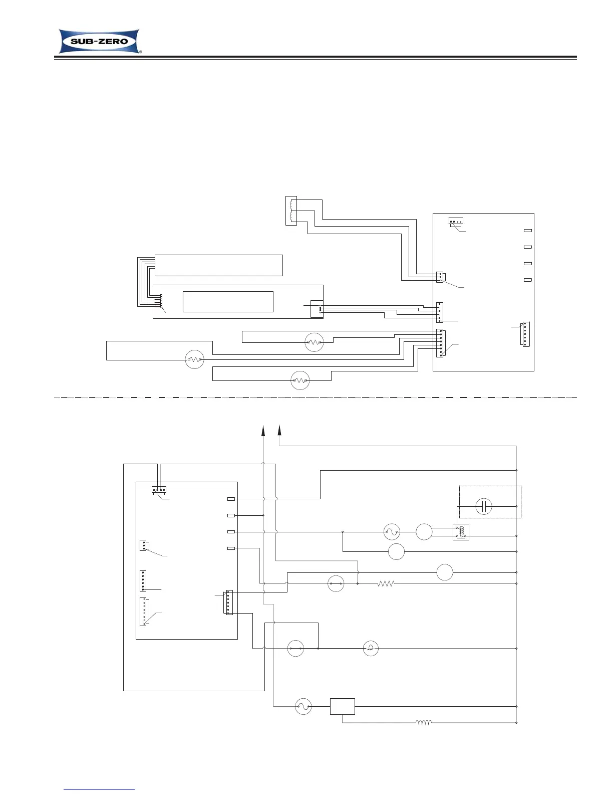
Figure 3-1. UC-24C Wiring Schematic
ELECTRONIC CONTROL SYSTEM OVERVIEW
Below is the wiring schematic for the model UC-24C, illustrating the components of the electronic control system.
• Manual input operations are performed at the control panel (membrane keypad).
• Temperatures and possible problems with the unit will appear in the control panel display.
• Monitoring, regulating and controlling functions take place at the main control board.
The entire electronic control system is described in greater detail on the following pages.
NOTE: For more detailed electrical diagrams refer to the wiring diagram and schematic supplied with the unit.