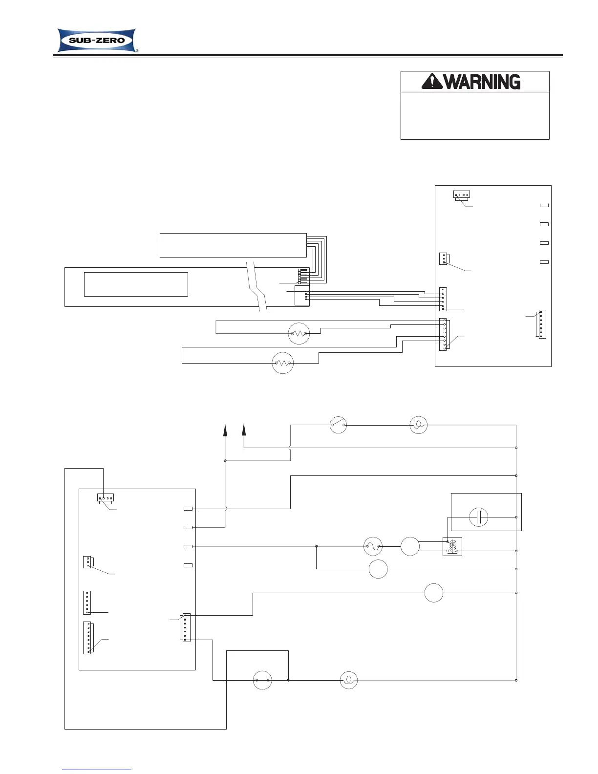
-This wiring information is provided for use by qualified
service personnel only.
-Disconnect appliance from electrical supply before beginning service.
-Be sure all grounding devices are connected when service is complete.
-Failure to observe the above warnings may result in
severe electrical shock.
PIN 1
RELAY
YELLOW
STARTING
RED
ORANGE
(WHEN
USED)
CAPACITOR
COMPRESSOR
REF LIGHT
SWITCH
WHITE
BLACK
PROTECTOR
PIN 1
THERMISTOR
REFRIGERATOR
BLUE W/BLACK STRIPE
WHITE
ORANGE W/RED STRIPE
J5
J3
J2
J4
J6
J3
P2
P1
P3
P4
M
M
M
ORANGE
PURPLE
ORANGE
PIN 1
PIN 1
PIN 1
YELLOW
MAIN BOARD
PIN 1
ORANGE
PIN 1
WHITE
REF (TOP)
LIGHT
REF FAN MOTOR
OVERLOAD
CONDENSER FAN
RED
COMPRESSOR
RUNNING
MAIN BOARD
WHITE
MEMBRANE KEYPAD
THERMISTOR
EVAPORATOR
NEUTRAL
HIGH VOLTAGE SCHEMATIC
L1
115 VOLTS
60 CYCLES
DISPLAY BOARD
BLUE W/BLACK STRIPE
PIN 1
BLUE W/RED STRIPE
PIN 1
PIN 1
PIN 1
LOW VOLTAGE SCHEMATIC
PIN 1
LIGHTS
PINK
WHITE
REF LIGHT
SWITCH
LIGHT TUBE SWITCH
(UC-24B ONLY)
J4
J5
J3
J6
J2
P3
P2
P1
P4
DISPLAY
J2
P/N 7002555 REV A
WIRING SCHEMATIC
MODEL UC24-B, UC-24R, UC-24RO
Wire Diagrams & Schematics
Under Counter (UC-24) Series
10-5
#7003933 - Revision B - November, 2007