400 Series
400 Series
Component Access and Removal
6-12
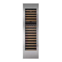
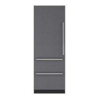
Figure 6-23. Evaporator
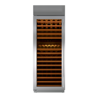
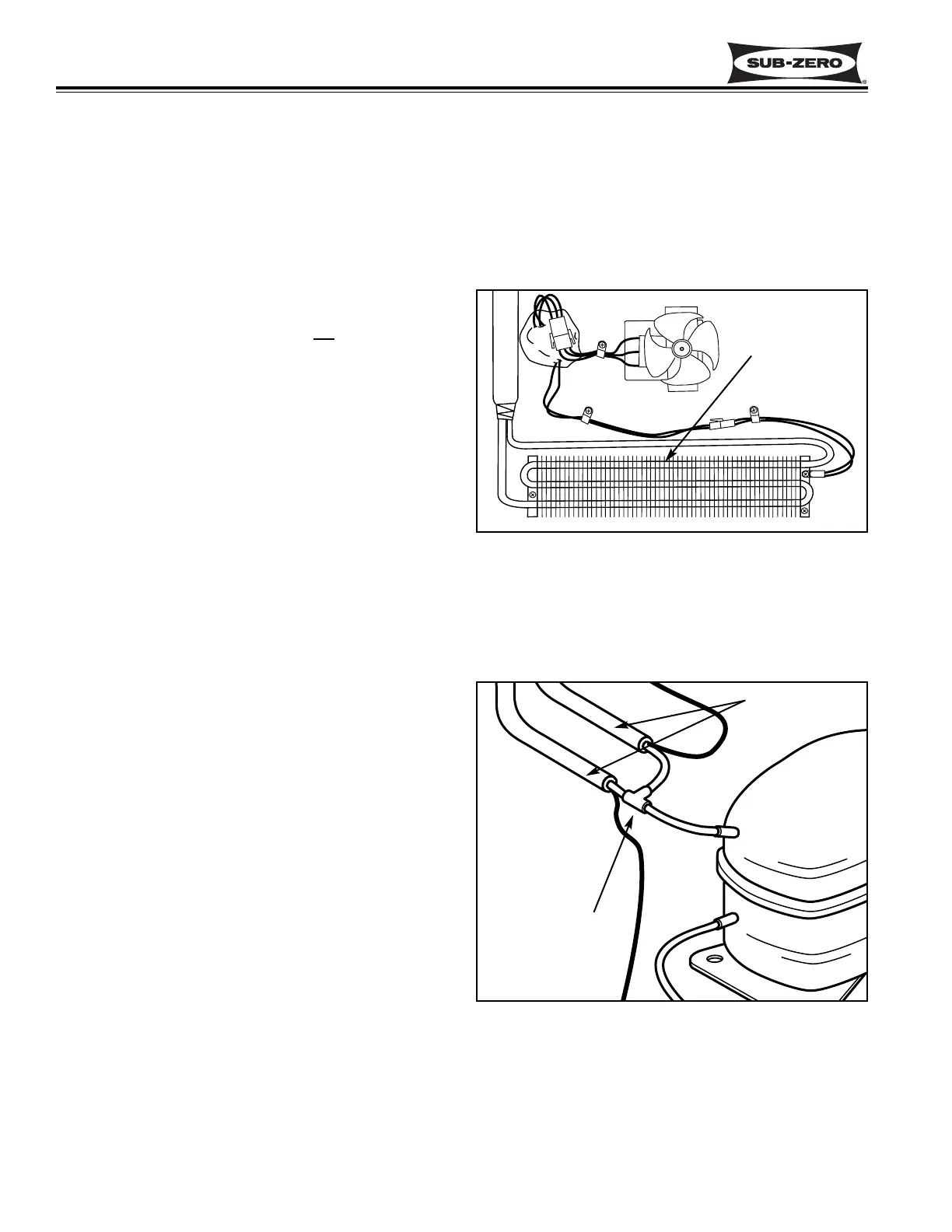
Figure 6-24. Suction “T” Connection
Heat Exchangers
“T” Connection
(Under cabinet)
MODEL 424 SEALED SYSTEM
COMPONENT ACCESS AND REMOVAL:
An attempt has been made to arrange these instruc-
tions in such a way as to simulate which components
would need to be removed first in order to gain access
to other components. When following a component
removal procedure, it may be necessary to reference
another removal procedure towards the front of this
section.
NOTE: To access and remove any sealed system
component on a Model 424, the unit will
need to be
pulled from its installation. See TIPPING WARNING at
beginning of this section. If removing a model 424
from its installation, an anti-tip bracket and a countertop
bracket may have been used to make a solid installa-
tion. (See Figures 2-2) If the brackets were not used,
shims may have been wedged along the sides and top.
Also see HOT COMPRESSOR & TUBING CAUTION
and SHARP FINS CAUTION at beginning of this sec-
tion.
NOTE: Always replace the filter-drier when servicing
the sealed system.
Upper Evaporator Assembly Access and Removal
(Model 424)
The evaporator assembly consists of the evaporator
and heat exchanger. The evaporator is mounted to the
rear wall with Phillips-head screws, and the heat
exchanger is routed out the back wall down to the unit
tray where the capillary tube is attached to the refriger-
ant valve, and the suction line is attached to a "T" con-
nection that runs to the compressor suction port. (See
Figures 6-23, 6-24, 6-25)
After evacuating the refrigerant from the sealed system,
begin the access and removal procedure inside the unit
by removing the two wine racks, all cabinet slides, cabi-
net slide spacers and cabinet slide support spacers in
the upper compartment. Then, remove the evaporator
fan cover mounting screws, the evaporator fan cover
and the evaporator cover. Extract the evaporator
mounting screws. Now, remove the access panel from
the bottom back of the unit and the heat exchanger
duct cover. Remove the door closer (See DOOR
CLOSER WARNING at beginning of this section.)
Extract the four screws securing the unit tray to the
cabinet on the left side, and loosen the four screws on
the right side. Separate the unit tray from the cabinet
by leaning the cabinet to the right, then insert a spacer
between the cabinet and unit tray. (A small piece of
2x4 lumber works well.) (See Figure 6-8) Cut the cap
tube from the outlet port of the refrigerant valve and cut
the suction line from the "T" connector. Then, pull the
evaporator assembly from the front of the unit.
Evaporator
Assembly
(Includes Heat
Exchanger)
 Loading...