400 Series
400 Series
Component Access and Removal
6-14
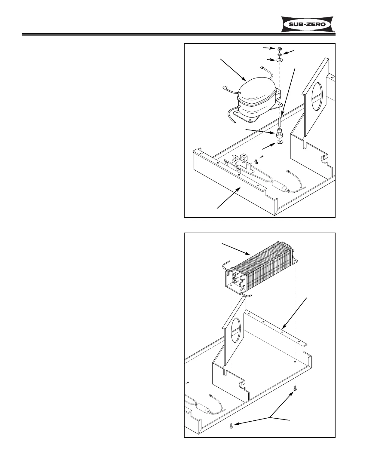
Compressor Access and Removal (Model 424)
The compressor is located at the back of the unit tray.
(See Figure 6-26)
After evacuating the refrigerant from the sealed system,
begin the access and removal procedure by removing
the access panel from the bottom back of the unit.
Remove the door closer (See DOOR CLOSER WARN-
ING at beginning of this section.) Extract the four
screws securing the unit tray to the cabinet on the left
side, and loosen the four screws on the right side.
Separate the unit tray from the cabinet by leaning the
cabinet to the right, then insert a spacer between the
cabinet and unit tray. (A small piece of 2x4 lumber
works well.) (See Figure 6-8) Disconnect the compres-
sor electricals from the compressor. Remove the four
nuts from the compressor mounting studs. Cut the suc-
tion tube and discharge tube approximately 1-1/2" from
the compressor and lift the compressor off of the
mounting studs.
Condenser Access and Removal (Model 424)
The condenser is located at the front right of the unit
tray, and is held in place with screws passing up from
under the unit tray into the condenser brackets. (See
Figure 6-27)
After evacuating the refrigerant from the sealed system,
begin the access and removal procedure by removing
the access panel from the bottom back of the unit.
Remove the door closer (See DOOR CLOSER WARN-
ING at beginning of this section.) Extract the four
screws securing the unit tray to the cabinet on the right
side, and loosen the four screws on the left side.
Separate the unit tray from the cabinet by leaning the
cabinet to the left, then insert a spacer between the
cabinet and unit tray. (A small piece of 2x4 lumber
works well.) (See Figure 6-8) Remove the condenser
mounting screws. Cut the inlet tube and outlet tube
approximately 3" from the condenser and lift the con-
denser up and out.
Figure 6-26. Compressor
Figure 6-27. Condenser
Compressor
Unit Tray
Condenser
Screws
Unit Tray
Nut
Lock Washer
Washer
Sleeve
Grommet
Washer