400 Series
400 Series
Component Access and Removal
6-15
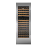
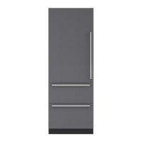
MODELS 427 & 427R
NOTE: Since the models 427 and 427R are similar, the access and removal section for these models has been
grouped together. The model(s) covered will be listed between brackets after the heading.
MODEL 427 & 427R EXTERIOR COSMETIC AND MECHANICAL COMPONENT REMOVAL:
An attempt has been made to arrange these instructions in such a way as to simulate which components would
need to be removed first in order to gain access to other components. When following a component removal proce-
dure, it may be necessary to reference another removal procedure towards the front of this section.
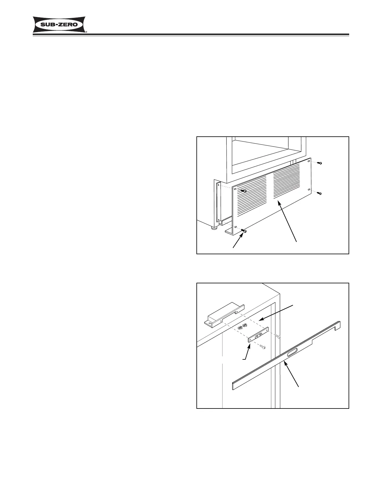
Figure 6-28. Kickplate/Grille Removal
Figure 6-29.
Light Switch & Fan Switch Access
Kickplate / Grille
Screw (4)
Light & Fan Switch
Top Molding
Switch Bracket
Kickplate/Grille Removal (Models 427 & 427R)
The kickplate/grille is held in place by four screws pass-
ing through it into adjustable kickplate brackets. To
remove the kickplate/grille, extract the four screws, two
on each side, and pull the kickplate grille forward. (See
Figure 6-28)
NOTE: For the 427R, it may be necessary to remove
the bottom drawer to gain access to the kickplate/grille.
Wine Compartment Light and Fan Switches Access
and Removal (Models 427 & 427R)
The wine compartment light and fan switches protrude
through the top trim molding, just above the door. Tabs
on the switches hold the switches in a switch bracket.
And, the bracket is attached to the switch enclosure
with two screws.
NOTE: See ELECTRIC SHOCK WARNING at begin-
ning of this section.
To access and remove a light and/or fan switch, you will
need to remove the side molding strips. Now, remove
the top molding by pulling the top of the molding for-
ward, then lift up. Remove the two screws from the
switch bracket and pull the bracket forward. (See
Figure 6-29) Disconnect the electrical leads from the
switch being removed. Depress the tabs on the side of
the switch being removed and push the switch out of
the bracket.