400 Series
400 Series
Component Access and Removal
6-17
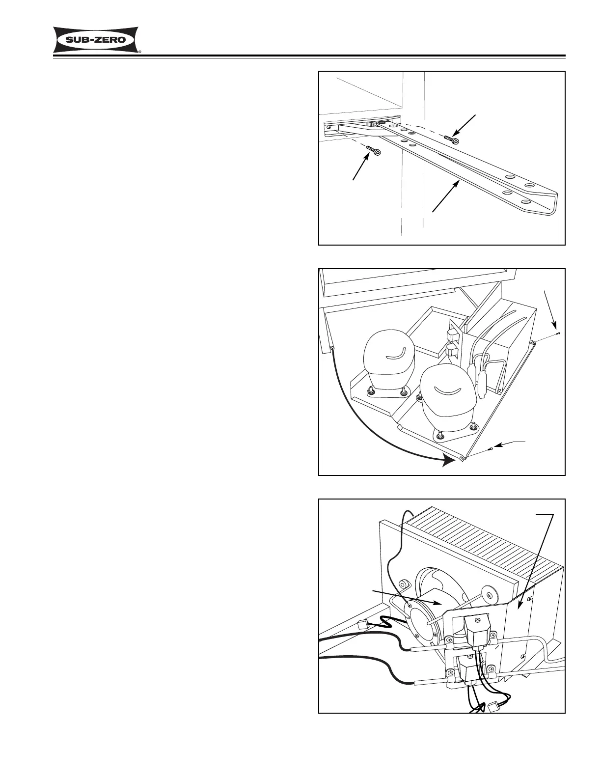
Figure 6-33. Hinge Assembly Removal
Figure 6-34. Unit Tray Removal
Figure 6-35. Condenser Fan Assembly
Hinge Arm
Bolt
Bolt
Pull unit
tray out and
pivot to the right
Screw
Condenser
Fan Assy
Refrigerant Valve
Bracket
Screw
NOTE: See HEAVY DOOR WARNING and DOOR
CLOSER CAUTION at beginning of this section.
To remove a hinge assembly, you will need to remove
the door first. Begin by opening the door and removing
both hinge covers. Then, with an Allen-head wrench,
remove the four door mounting screws from the top
hinge. Now, close the door and remove the four door
mounting screws from the bottom hinge, and lift the
door from the unit. (See Figure 6-30)
NOTE: On the model 427R you will need to remove the
top drawer to access the door mounting screws at the
bottom hinge. (See Drawer Assembly Removal - 427R
ONLY, on previous page.)
Now, extract the Allen-head bolts from the appropriate
hinge mounting bracket and pull the hinge from the unit.
(See Figure 6-33)
Condenser Fan Assembly Access and Removal
(Models 427 & 427R)
The condenser fan motor is attached to a three legged
condenser fan bracket by screws. The right leg of the
fan bracket hooks over a spacer on the fan shroud.
The two left legs of the fan bracket are secured to the
fan shroud by screws into wellnuts.
NOTE: See ELECTRIC SHOCK WARNING at begin-
ning of this section.
To access and remove the condenser fan assembly,
you will need to remove the kickplate/grille and slide the
unit tray out. To slide the unit tray out, extract the two
screws that secure the tray to the cabinet, located at
the bottom left and right of the cabinet. Slide the unit
tray out half way and disconnect the compressor, con-
denser fan, solenoid and ground wire electrical leads.
Continue sliding the tray out while pivoting it to the
right. (See Figure 6-34)
NOTE: Move tray slowly and observe the sealed sys-
tem tubing. Care must be taken to not kink any of the
tubing.
Now, extract the screws from the left legs of the con-
denser fan bracket.
NOTE: You will need to loosen the screws securing the
refrigerant valve bracket and push the bracket back
slightly and lift up slightly to gain access to the bottom
left leg of the condenser fan bracket.
Then, unhook the right condenser fan bracket leg by
pushing the assembly to the right, then lift up and out.
(See Figure 6-35) The condenser fan motor can now
be removed from the bracket by extracting the screws
in the back side of the fan motor. The fan blade can be
removed from the fan motor by turning the flat-nut on
the fan motor shaft counterclockwise, then pull the nut
and blade from the shaft.
 Loading...