400 Series
400 Series
Component Access and Removal
6-18
Figure 6-36.
Refrigerant Valve Solenoid
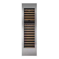
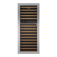
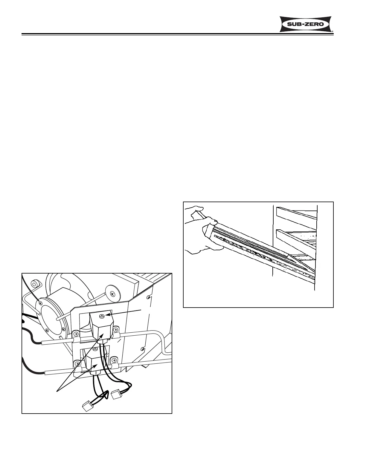
Figure 6-37. Wine Rack Assembly Removal
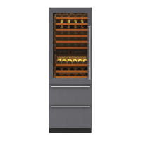
MODEL 427 & 427R INTERIOR COSMET-
IC COMPONENT ACCESS AND REMOVAL:
An attempt has been made to arrange these instruc-
tions in such a way as to simulate which components
would need to be removed first in order to gain access
to other components. When following a component
removal procedure, it may be necessary to reference
another removal procedure towards the front of this
section.
Wine Rack Assembly removal (Models 427 & 427R)
To remove a wine rack assembly, pull the rack forward
until it stops. Remove any wine bottles on the rack. Lift
the front of the wine rack up while pulling forward. After
the indentations on the wine rack clear the rollers on
the cabinet slides, lower the front of the wine rack while
continuing to pull forward, then lift the rear of the rack
up and out. (See Figure 6-37)
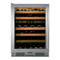
Wine Storage Cabinet Slide and Slide Spacer
Removal (Models 427 & 427R)
Cabinet slides in the wine storage compartments are
attached to the side wall and false wall of the wine com-
partments with screws. If the cabinet slide is attached
to the handle side of the compartment, a small plastic
slide spacer is placed between the front of the slide and
the side wall. If the cabinet slide is on the hinge side,
it is attached directly to the false wall.
To remove a cabinet slide from a wine storage compart-
ment, you must first remove the wine rack. Then,
extract the mounting screws and pull the cabinet slide
(and slide spacer if on handle side) from the wall. (See
Figure 6-38)
Screw
Solenoids
Lift front while pulling forward.
After indentations clear rollers,
lower front, pull forward, lift rear.
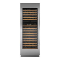
Refrigerant Valve Solenoid Access and Removal
(Models 427 & 427R)
The refrigerant valve solenoids are attached to the tops
of the refrigerant valves with screws. The refrigerant
valves are located to the right of the compressor(s) on
the unit tray, and are held to the valve bracket with P-
clamps and screws. The top valve is for the upper wine
storage compartment and the bottom valve is for the
lower wine storage compartment.. (See Figure 6-36)
NOTE: See ELECTRIC SHOCK WARNING and HOT
TUBING CAUTION at beginning of this section.
To access and remove the condenser fan assembly,
you will need to remove the kickplate/grille and slide the
unit tray out. To slide the unit tray out, extract the two
screws that secure the tray to the cabinet, located at
the bottom left and right of the cabinet. Slide the unit
tray out half way and disconnect the compressor, con-
denser fan, solenoid and ground wire electrical leads.
Continue sliding tray out while pivoting it to the right.
(See Figure 6-34)
NOTE: Move tray slowly and observe the sealed sys-
tem tubing. Care must be taken to not kink any of the
tubing.
Now, disconnect the electrical leads of the valve sole-
noid being removed. Remove the screw at the top of
the solenoid and lift the solenoid up off the valve.
NOTE: You may need to twist the refrigerant valve in
the P-clamps slightly to allow the solenoid to be
removed.
 Loading...