400 Series
400 Series
Component Access and Removal
6-32
Panel Grille Assembly Removal (Model 430)
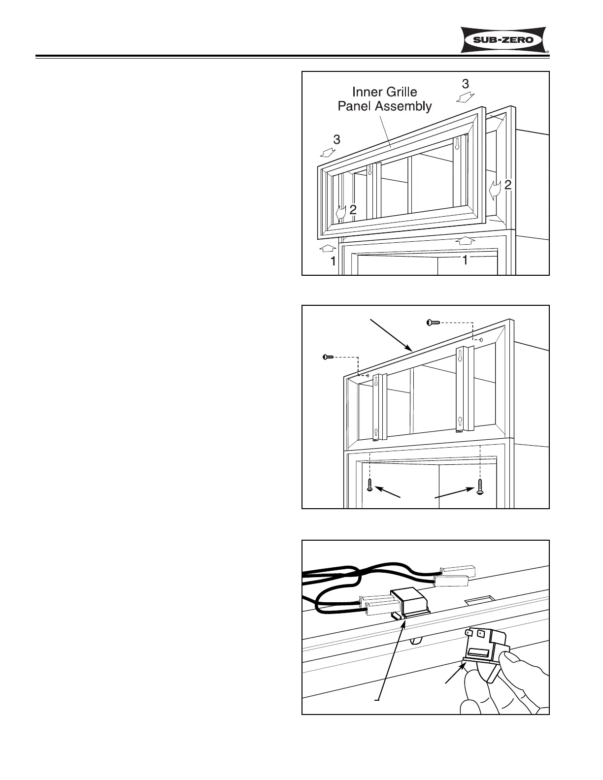
The panel grille assembly consists of an outer and
an inner grille frame. The outer grille frame attaches
to the unit, while the inner grille frame(which accepts
a decorative panel) is easily removable for condens-
er cleaning purposes. There are pegs on the back
side of the inner grille frame which fit in key-hole
slots in the outer grille frame.
To remove the inner grille frame, lift assembly up (1)
and pull out of key-hole slots at the bottom (2).
Then, pull down and out of key-hole slots at the top
(3). (See Figure 6-70)
To remove the outer grille frame, remove the inner
grille frame first. Now, opening unit door(s) and
extract the grille screws which pass up through the
top mainframe extrusion into bottom extrusion of
outer grille frame. Now, extract the screws at the top
front of outer grille frame and lift frame off. (See
Figure 6-71)
Light Switch and Fan Switch Access and
Removal (Model 430)
The light and fan switches are mounted to the top
mainframe and held in place by tabs on the sides of
the switches. A switch cover over the top of the
switches is held in place with a screw.
NOTE: See ELECTRIC SHOCK WARNING at
beginning of this section.
To access and remove the light and/or fan
switch(es), the unit grille will need to be removed
first. Now, remove the switch enclosure directly
behind the top mainframe extrusion by extracting the
retaining screw. Tilt the back of the switch enclosure
forward and lift up. Now unplug the wires from the
switch being removed. Open the door. Depress the
tab on the side of the switch while pushing the switch
down and out of the opening in the mainframe extru-
sion. (See Figure 6-72)
Figure 6-72. Light Switch and Fan Switch
Figure 6-70. Inner Panel Grille Removal
Figure 6-71. Outer Panel Grille Removal
Outer Frame
Screws
Light Switch
Fan Switch