400 Series
400 Series
Component Access and Removal
6-7
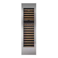
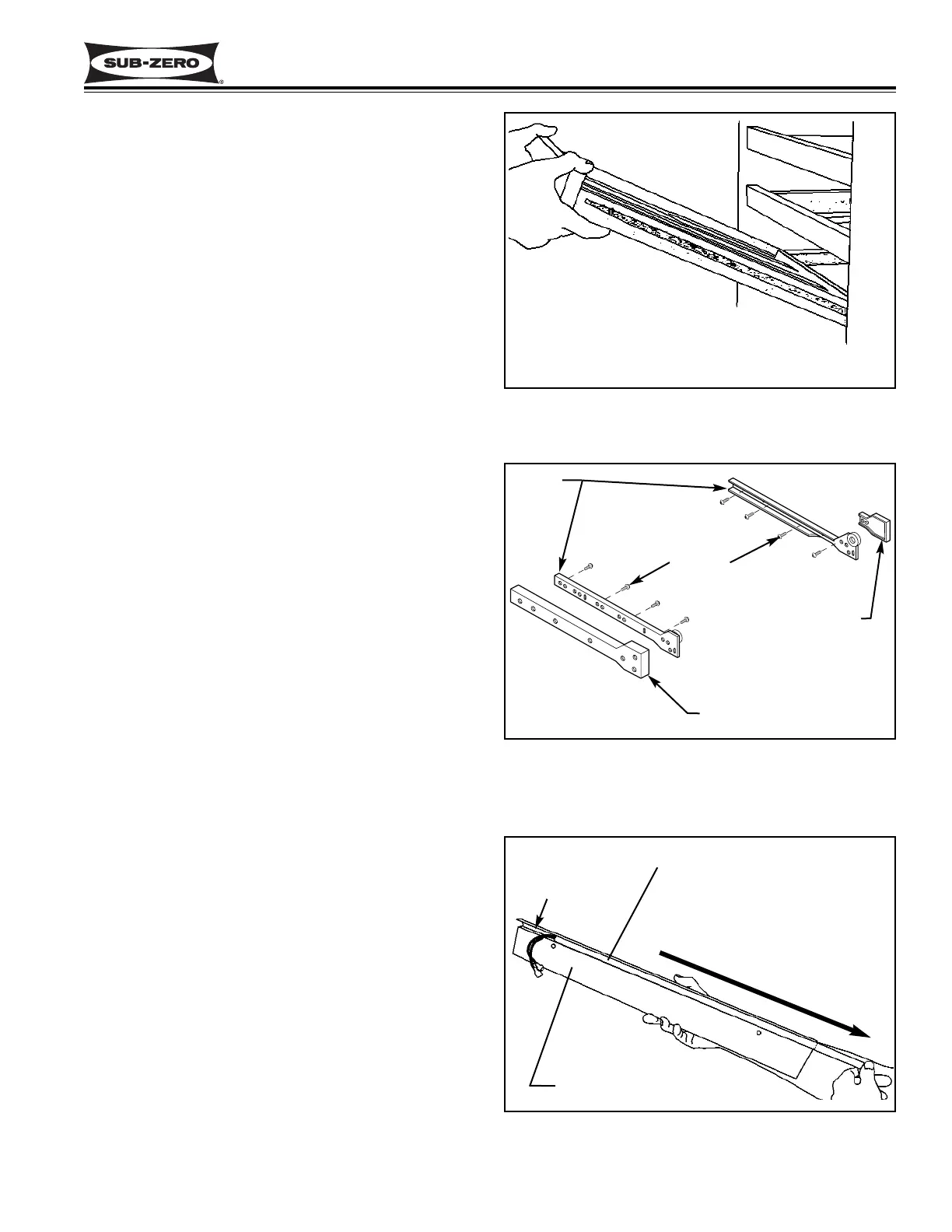
Figure 6-9. Wine Rack Assembly Removal
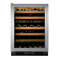
Figure 6-10. Cabinet Slide, Slide Support
Spacer & Slide Spacer Removal
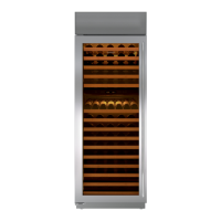
Figure 6-11. Upper Light Strip Removal
MODEL 424 INTERIOR COSMETIC
COMPONENT ACCESS AND REMOVAL
An attempt has been made to arrange these instruc-
tions in such a way as to simulate which components
would need to be removed first in order to gain access
to other components. When following a component
removal procedure, it may be necessary to reference
another removal procedure towards the front of this
section.
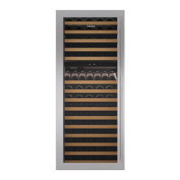
Wine Rack Assembly Removal (Model 424)
To remove a wine rack assembly, pull the rack forward
until it stops. Remove any wine bottles on the rack.
Now, lift the front of the rack up while pulling forward.
After the indentations on the wine rack clear the rollers
on the cabinet slides, lower the front of the wine rack
while continuing to pull forward, then lift the rear of the
rack up and out. (See Figure 6-9)
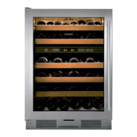
Cabinet Slide, Slide Spacer and Slide Support
Spacer Removal (Model 424)
Cabinet slides are attached to the side walls of the wine
compartments with screws. If the cabinet slide is
attached to the handle side of the compartment, a small
plastic slide spacer is placed between the front of the
slide and the side wall. If the cabinet slide is attached
to the handle side, a wide plastic slide support spacer is
placed between the slide and the wall.
To remove a cabinet slide, you must first remove the
wine rack. Then, extract the Phillips head cabinet slide
mounting screws and pull the cabinet slide and slide
spacer or slide support spacer from the wall. (See
Figure 6-10)
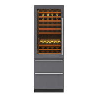
Upper Light Strip Access and Removal (Model 424)
NOTE: See ELECTRIC SHOCK WARNING at begin-
ning of this section.
The light strip is held in the channel of the light strip
housing. To remove the upper light strip, remove the
top wine rack assembly first. Then, extract the two light
strip housing mounting screws securing the housing to
the ceiling. Lower the light strip housing down, discon-
nect the light strip electrical leads and extract the screw
securing the ground wire to the housing. Now, slide the
light strip out the end of the channel. (See Figure 6-11)
NOTE: When reinstalling the light strip housing, care
must be taken to ensure that all wire leads are tucked
back behind the light strip housing before resecuring it
to the ceiling.
Lift front while pulling forward.
After indentations clear rollers,
lower front, pull forward, lift rear.
Slide Support Spacer
Slide
Screws
Slide light strip out
end of the channel.
Channel
Light Strip
Light Strip Housing
Slide Spacer
 Loading...