400 Series
400 Series
Component Access and Removal
6-6
Condenser Fan Assembly Access and Removal
(Model 424)
To access the condenser fan, the unit will need to be
pulled from its installation. (See TIPPING WARNING at
beginning of this section.)
NOTE: If removing a model 424 from its installation, an
anti-tip bracket and a countertop bracket may have
been used to make a solid installation. (See Figures 2-
2) If the brackets were not used, shims may have been
wedged along the sides and top.
Remove the access panel from the bottom back of the
unit, disconnect the fan electrical leads, and extract the
grounding screw from the ground wire.
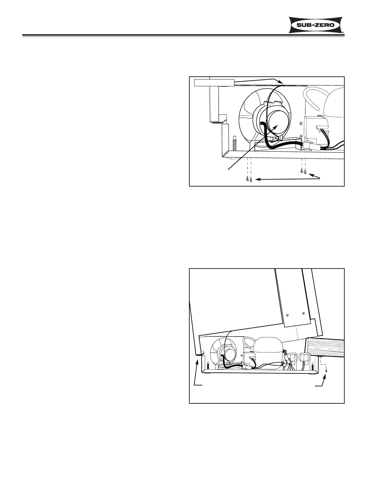
The condenser fan bracket is secured to the unit tray by
screws passing up from under the unit tray into thread-
ed stand-offs. (See figure 6-7) Lean the unit to the
front or side and extract the bracket mounting screws
and lift fan assembly from the unit tray.
The fan motor can now be removed from the fan brack-
et by extracting the fan mounting screws. The fan
blade can be removed from the fan motor by turning the
flat-nut on the fan motor shaft counterclockwise, then
pull the blade from the shaft.
Refrigerant Valve Solenoid Access and Removal
(Model 424)
To access the refrigerant valve solenoids, the unit will
need to be pulled from its installation. (See TIPPING
WARNING at beginning of this section.)
NOTE: If removing a model 424 from its installation, an
anti-tip bracket and a countertop bracket may have
been used to make a solid installation. (See Figures 2-
2) If the brackets were not used, shims may have been
wedged along the sides and top.
Remove the access panel from the bottom back of the
unit. Remove the door closer (See DOOR CLOSER
WARNING at beginning of this section.) Extract the
four screws securing the unit tray to the cabinet on the
left side, and loosen the four screws on the right side.
Separate the unit tray from the cabinet by leaning the
cabinet to the right, then insert a spacer between the
cabinet and unit tray. (A small piece of 2x4 lumber
works well.) (See Figure 6-8) Disconnect the electrical
leads to the solenoid being removed. (See ELECTRI-
CAL SHOCK WARNING at beginning of this section.)
The solenoid is secured to the refrigerant valve with a
screw at the top. Remove the screw and lift the sole-
noid up off the valve.
Figure 6-7. Condenser Fan Assembly
Figure 6-8. Unit Tray Component Access
Screws
Ground Screw
Condenser
Fan Assembly
Loosen Screws
on this side
Remove Screws
on this side