-
30
-
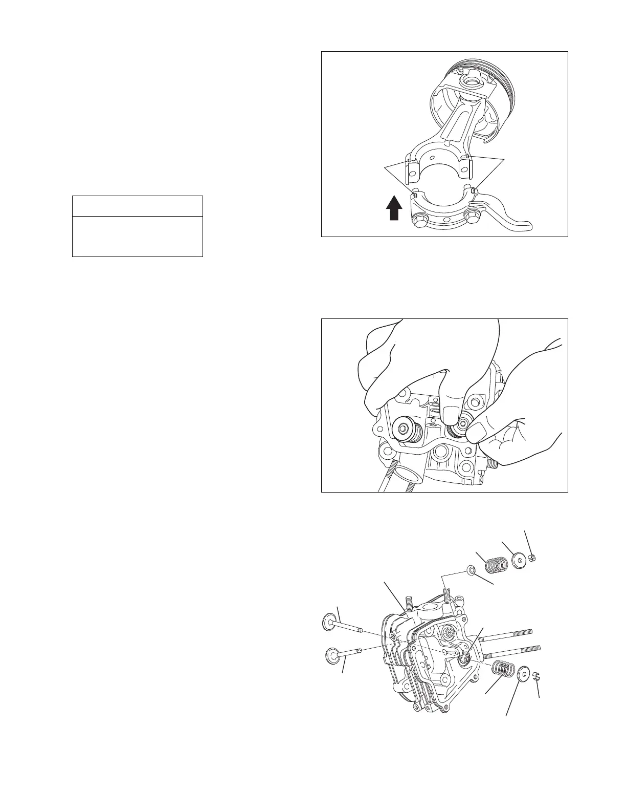
(b) Rotate the crankshaft down to the bottom dead
center and lightly tap the piston head until the
large end of the connecting rod touches the
crank pin.
(c)
To mount the connecting rod, line up the matching
marks and fit the clinch portions firmly together.
M8 bolt (12mm box wrench)
Fig.5-37
ALIGNMENT
MARKS
ALIGNMENT
MARKS
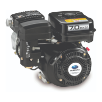
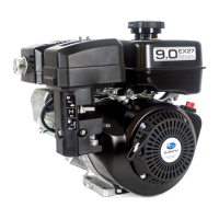
(6) INTAKE AND EXHAUST VALVES
Takethefollowingpointsintoaccountwhen
mountingtheintakeandexhaustvalvesonthe
cylinderhead.
NOTE1:Replacethevalvewithanewoneif
itshowssignsofwear.
(RefertotheSTANDARDREPAIR
TABLESonpage76and77.)
NOTE2:Carefullyscrapeoffanycarbon
depositsonthecombustionchamber.
Apply
oiltothevalvestemsbeforemountingthe
intakeandexhaustvalves.Insertthe
valvesinthe
cylinderheadandplaceiton
alevel
workbench.Next,mountthevalve
springs,thespringretainersandcollet
valves.(Mountthestemsealontheintake
valveguide.)
Fig.5-39
Fig.5-38
EXHAUST VALVE
INTAKE VALVE
CYLINDER HEAD
VALVE
SPRING
VALVE SPRING
COLLET
VALVE
COLLET VALVE
SPRING
RETAINER
SPRING RETAINER
STEM SEAL
(INTAKE ONLY)
RETAINER PLATE
(EXHAUST ONLY)
(d) Check for free movement of the connecting rod
by turning the crankshaft slowly.
Tightening torque
22.5 - 27.5 N
・
m
(225 - 275
kgf
・
cm
)
(16.3 - 19.9 ft
・
lb.)