Suburban DynaLine Owner's Manual 10/2017 Rev.1 6
You as the owner/user should inspect the unit periodically during the
heating season. Particular attention should be given to the following:
A. Periodically observe the main burner ame to assure it is burning with a hard
blue ame with well-dened burner ports. (See Figure 16.) If ame appears
yellow or burner has a lazy ame, shut furnace down and contact a qualied
service person.
B. Periodically inspect the vent for obstructions or presence of soot. Soot is
formed whenever combustion is incomplete. This is your visual warning that
the furnace is operating in an unsafe manner. If soot is present, immediately
shut furnace down and contact your dealer or a qualied service person.
C. Circulating air through the front grille must not be blocked. Keep lter clean to
assure adequate air ow.
The removable, washable type lter should be cleaned or replaced several
times during the year. This will depend upon the usage and location of the unit.
Dirty lters restrict air ow across the heat exchanger and coils. This results
in inadequate cooling and shortens the life expectancy of the heat exchanger,
motors and compressor.
FILTER REMOVAL
1. The lter is located behind the cabinet front. Remove cabinet front by lifting
up. Slide lter up until free of left tab.
2. Filter may be washed in a soapy solution and rinsed in clear water. Let lter
dry before reinstalling it on the unit.
3. Reinstall lter.
NOTE: NEVER OPERATE UNIT WITH FILTER REMOVED. Evaporator coil and/
or drain pan may become restricted.
4. Reinstall cabinet front.
CLEANING CONDENSER COIL
NOTE: Work should be performed by a qualied service person.
NOTE: Use a coil cleaner recommended by one of these manufacturers:
Nu Calgon, Rector Seal
NOTE: Make sure gas and electrical supply is "OFF to unit.
1. Remove cabinet front. Remove four(4) screws from left and right side panels;
set aside for reinstallation.
2. Remove unit from wall sleeve.
3. After unit is removed, move to an open area.
4. To begin process of cleaning the condenser coil, remove the following screws:
a) Remove four(4) screws from condenser housing braces. (see A gure 17)
Set braces aside for reinstallation.
b) Remove condenser coil cover- (2) additional screws. (see B gure 17) Set
aside for reinstallation.
5. Motor should be covered during cleaning.
6. Be sure to follow the manufacturers instructions in the use and disposal of
their products.
7. Apply the cleaning solution to the coil by trickle method across the top of the
coil until solution runs from drain.
8. The coil can then be cleaned with a water hose by back washing it until all dirt
is drained from weep holes in the chassis. Unit should be tilted back so water
will drain to the back. Allow unit to air dry.
9. Reassemble condenser coil cover and braces.
10. Reinstall unit into wall sleeve.
11. Reinstall cabinet front.
NOTE: After unit is reinstalled, check for gas leaks and verify proper operation in
heat and A/C modes.
Listed below are several safety related items that you should follow during the
heating season to assure continued safe operation of the furnace.
1. Never operate the unit if you smell gas. Do not assume that the smell of gas is
normal. Any time you detect the odor of gas, it is to be considered life threatening
and corrected immediately. (See safety notice on front cover of this manual.)
2. Immediately shut unit down and call a service agency if unit cycles erratically
or delays on ignition.
WARNING! Should overheating occur, or the gas supply fail to shut off, shut off the
manual gas valve to the appliance before shutting off the electrical supply.
3. Do not restrict the ow of combustion air or the warm air circulation to the unit.
To do so could cause personal injury and/or death.
WARNING! Do not install screens over the vent for any reason. Screens will become
restricted and cause unsafe furnace operation.
4. Keep unit clean. More frequent cleaning may be required due to excessive lint
from carpeting, bedding material, etc. It is imperative that control compartments,
burners and circulating air passageways of the appliance be kept clean.
5. Keep the furnace area clear of any combustible materials, gasoline or other
ammable vapor and liquids.
6. Do not use this appliance if any part has been submerged under water.
Immediately call a qualied service technician to inspect the appliance and
to replace any part of the control system and any gas control that has been
submerged under water.
7. Always follow the operating instructions. Do not deviate from the step-by-step procedures.
8. Never attempt to repair damaged parts. Always have them replaced by a
qualied service agency.
9. Never attempt to repair the furnace yourself. Seek the help of a qualied service person.
10. The room air motor, the condenser motor and the combustion air motor are
maintenance free motors and require no oiling.
GENERAL NOTES
The efciency rating of this unit is a product thermal efciency rating determined
under continuous operating conditions and was determined independent of any
installed system.
Children and adults should be alerted to the hazards of high surface
temperatures and should stay away to avoid burns or clothing ignition.
Young children should be carefully supervised when they are in the same
room as the unit.
Clothing or other ammable material should not be placed on or near
the unit.
Any safety screen or guard removed for servicing the unit must be
replaced prior to operating the unit.
Installation and repairs should be done by a qualied service person.
The appliance should be inspected before use and at least annually by a
qualied service person. More frequent cleaning may be required due to
excessive lint from carpeting, bedding material, etc. It is imperative that
control compartments, burners and circulating air passageways of the
appliance be kept clean.
Never operate unit with lter removed. Evaporator coil and/or drain pan
may become restricted.
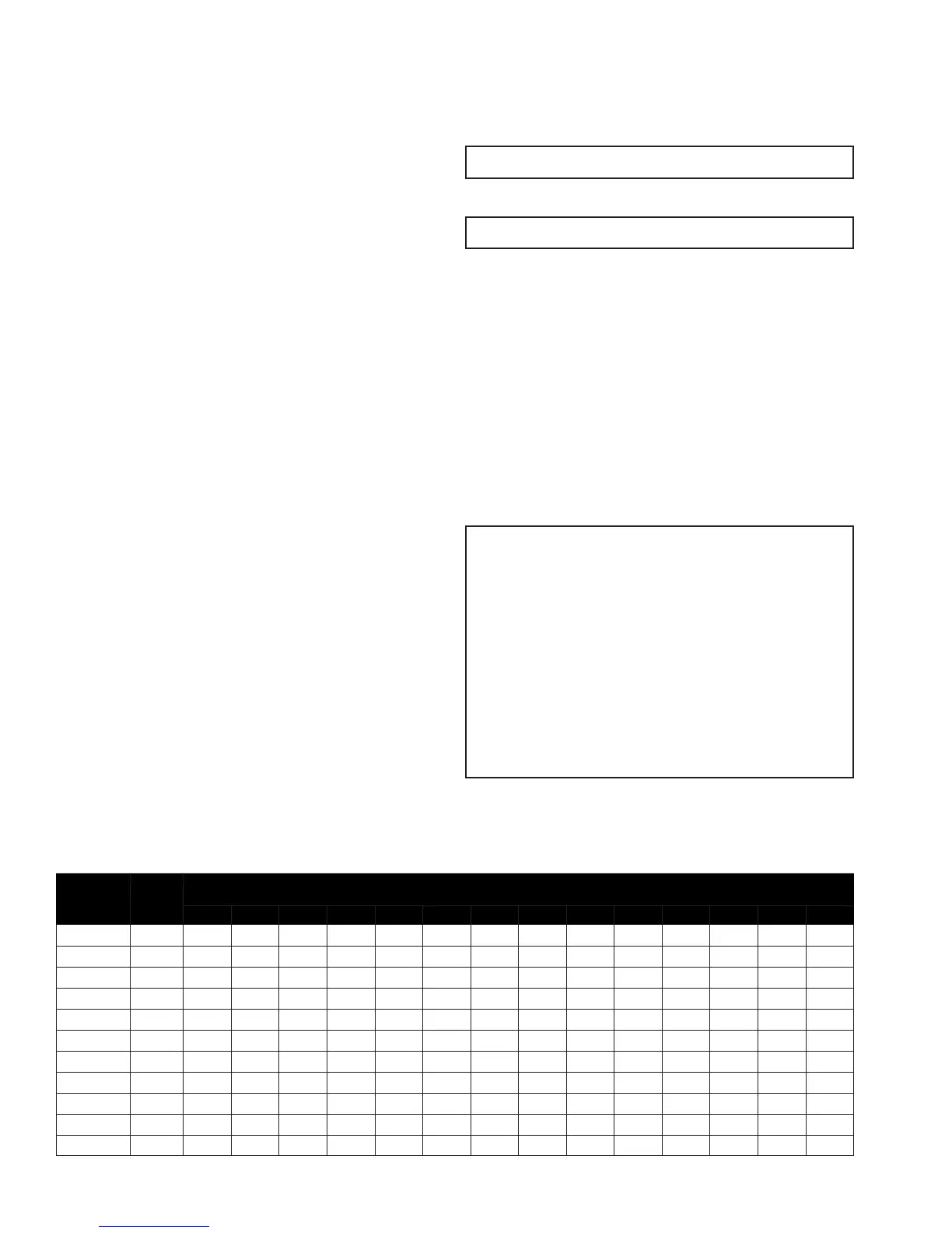
Maximum Capacity of Pipe in Cubic Feet of Gas per Hour for Gas Pressures of 0.5 PSIG or Less and a Pressure Drop of 0.3 Inch Water Column
(Based on a 0.60 Specic Gravity Gas)
Nominal
Iron Pipe
Size, in Inches
Internal
Diameter,
in Inches
LENGTH OF PIPE, Feet
10 20 30 40 50 60 70 80 90 100 125 150 175 200
1/4 .364 32 22 18 15 14 12 11 11 10 9 8 8 7 6
3/8 .493 72 49 40 34 30 27 25 23 22 21 18 17 15 14
1/2 .622 132 92 73 63 56 50 46 43 40 38 34 31 28 26
3/4 .824 278 190 152 130 115 105 96 90 84 79 72 64 59 55
1 1.049 520 350 285 245 215 195 180 170 160 150 130 120 110 100
1 - 1/4 1.380 1,050 730 590 500 440 400 370 350 320 305 275 250 225 210
1 - 1/2 1.610 1,600 1,100 890 760 670 610 560 530 490 460 410 380 350 320
2 2.067 3,050 2,100 1,650 1,450 1,270 1,150 1,050 990 930 870 780 710 650 610
2 - 1/2 2.469 4,800 3,300 2,700 2,300 2,000 1,850 1,700 1,600 1,500 1,400 1,250 1,130 1,050 980
3 3.068 8,500 5,900 4,700 4,100 3,600 3,250 3,000 2,800 2,600 2,500 2,200 2,000 1,850 1,700
4 4.025 17,500 12,000 9,700 8,300 7,400 6,800 6,200 5,800 5,400 5,100 4,500 4,100 3,800 3,500
TABLE 2
 Loading...