SUBURBAN MANUFACTURING COMPANY
676 Broadway Street
Dayton, Tennessee 37321
INSTALLATION MANUAL
FOR MODELS
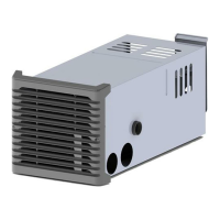
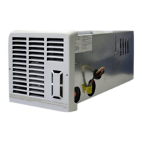
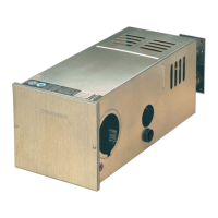
NT-12S • NT-16S • NT20S
The design of these furnaces has been certified for installation in recreational vehicles only. In order for these furnaces to operate in conformity
with generally accepted safety regulations, the installation instructions outlined in this book must be followed. Failure to comply with the
installation instructions will void any responsibility of Suburban Manufacturing Company. Your furnace was inspected before it left the factory. If
any parts are found to be damaged do not install the furnace. Any damages should be reported to the transportation company immediately and
the appropriate claims filed.
WARNING! Improper installation, adjustment, alteration, service or maintenance can
cause property damage, personal injury or loss of life. Refer to the installation
instructions and/or owners manual provided with this appliance. Installation and service
must be performed by a qualified installer, service agency or the gas supplier.
INSTALLATION INSTRUCTIONS
WARNING! Installation of this appliance must be made in accordance with
the written instructions provided in this manual. No agent, representative
or employee of Suburban or other person has the authority to change,
modify or waive any provision of the instructions contained in this
manual.
CAUTION: If possible, do not install the furnace to where the vent can be
covered or obstructed when any door on the trailer is opened. If this is not
possible, then the travel of the door must be restricted in order to provide
a 6" minimum clearance between the furnace vent and any door whenever
the door is open.
NOTE: The exhaust temperature of this furnace could discolor or warp some
materials. You should verify that the material used on the coach door, panel, or
cover will not discolor or warp from the exhaust temperature whenever any door,
panel, or cover is in the open position.
CAUTION: Due to the differences in vinyl siding, this appliance should not
be installed on vinyl siding without first consulting with the manufacturer of
the siding or cutting the siding away from the area around the appliance
vent.
CAUTION: In any installation in which the vent of this appliance can be
covered due to the construction of the RV or some special feature of the RV
such as slide out, pop-up, etc. always insure that the appliance cannot be
operated by setting the thermostat to the positive “OFF” position and
shutting off all electrical and gas supply to the appliance. Never operate
furnace with vent covered.
These furnaces must be installed and vented as described in this manual so that
the negative pressure created by the air circulating (return air) fan cannot affect
the combustion air intake or venting of any other appliance. It is imperative that
the products of combustion be properly vented to the atmosphere and that all
combustion air supplied to burner be drawn from the outside atmosphere. (See
“Installing Vent Assembly”.)
IMPORTANT: If this furnace is to be connected to a common duct system also
serving a cooling unit, a manual or automatic damper is required to prevent any
cold conditioned air from circulating back into the furnace. Cold air passing over
the furnace combustion chamber during the operation of the cooling unit can result
in the formation of condensation inside the furnace combustion chamber. This
condensation may promote corrosion and premature failure of the combustion
chamber.
NOTE: These furnaces shall be installed so the electrical components are
protected from water.
These furnaces will accommodate an installation depth from 23 3/8" minimum
(with standard vent tubes), to 30 1/8" maximum (with optional intake extension
tubes). (See Figure 1.)
Please adhere strictly to the installation instructions to insure proper installation
and safe operation, as well as adequate clearances for accessibility.
These furnaces are certified for use with propane/LP gas only. Gas supply
pressure for purposes of input adjustment:
Gas Minimum Maximum
Propane/LP 11" W.C.* 13" W.C.
*Water column
Return air
Return air must be from the living area of the coach.
NOTE: RV’s that have a wall of separation to a cargo area (Toy Box) to transport
internal combustion engine vehicles must not have return air opening from this
area.
An opening must be provided in the interior cabinetry of the coach directly in front
of the furnace. The opening must allow for free, unobstructed removal of the
furnace. This opening may be used as a means of providing circulating return air
to the furnace. Other openings may be used as well. The minimum return air to
the furnace must total 55 square inches free area. It is important that sufficient
return air be provided to insure normal heating and operation of the furnace. Also,
adequate clearances must be maintained around the furnace cabinet so that the
unit will be accessible for servicing. Failure to provide minimum return air as well
as an adequate opening for furnace removal voids the warranty.
In the USA, the installation must conform with local building codes. In the absence
of local building codes, refer to the latest edition of:
1-Standard for Recreational Vehicles ANSI A-119.2/NFPA 501C.
2-National Fuel Code ANSI Z223.1.
The furnace must be electrically grounded in accordance with the latest edition of
the National Electrical Code ANSI/NFPA No. 70. The installation of the furnace
shall be in accordance with any applicable local codes and regulations.
In Canada, the furnace must be installed in accordance with:
1-Standard CAN/CSA-Z240.6.2-M86 Electrical Requirements for Recreational
Vehicles.
3-Standard CAN/CSA-Z240.4.2-M86 Installation Requirements for Propane
Appliances and Equipment in Recreational Vehicles.
4-CAN/CGA-B149 Installation Codes
5-Any applicable local codes and regulations.
TO INSTALL THE FURNACE
1. Locate the furnace near lengthwise center of the coach. Do not install the
furnace with the vent facing toward the forward end of the coach.
2. Select a location for installation out of the way of wires, pipes, etc. that might
interfere with installation. Adhere to the following minimum clearances from the
furnace cabinet to combustible construction.
NT-12 • NT-16
Front 3/8" Floor 0"
NT-20S
Front 1" Floor 0"
Sides 1" Top 1" Sides 1" Top 1"
Back 0" Back 0"
NOTE: Side and top clearances may be 0" for through the wall installations up to
a maximum of 2 1/2" wall thickness (See Figure 3.)
3. When an appliance is installed directly on carpeting, tile or other combustible
material other than wood flooring, the appliance shall be installed on a metal or
wood panel extending the full width and depth of the appliance. If preferred, the
carpeting, tile or combustible materials, other than wood may be cut away the full
length and depth of the appliance plus the appliance minimum clearances to
combustibles.
4. Determine “X” dimension as shown in Figure 1 or 2 depending on model.
5. Determine “Y” dimension as shown in Figure 1 or 2.
6. If X-Y is less than 22 3/4" for Models NT-12 or NT-16, or 23 3/8" for Model NT-
20, then an opening 9 5/8" x 9 3/8" must be cut through the inner wall only. DO
NOT CUT THROUGH COACH SKIN. (See Figure 3.) Next, locate the center line
of the exhaust and intake tube. Cut two (2) 2 1/4" diameter holes through outer
skin as shown in Figure 5.
NOTE: Whenever the furnace cabinet is installed through the outside wall, the
return air louvers on the furnace cabinet must not be blocked. The maximum
projection of the furnace cabinet into the wall is 2 1/2". (See Figure 3.)
NOTE: Furnace cabinet approved for 0" clearance to combustible materials rear
2 1/2" of furnace cabinet.
7. If X-Y is 23 3/4" or greater for Model NT-12 or NT-16, or 23 3/8" or greater for
Model NT-20, two methods may be used to install the furnace. They are:
a. Cut a 4" x 7 1/2" opening through combustible wall as shown in Figure 4. DO
NOT CUT THROUGH TRAILER SKIN. Next, locate the center line of the exhaust
and intake tube. Cut two (2) 2 1/4" diameter holes through trailer skin.
(See Figure 5.)
b. If you do not wish to cut the 4" x 7 1/2" opening, locate the center line of the