SUBURBAN MANUFACTURING COMPANY
676 Broadway Street
Dayton, Tennessee 37321
423-775-2131
www.RVComfort.com
INSTALLATION MANUAL
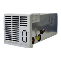
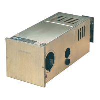
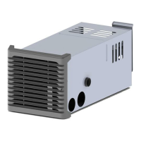
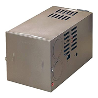
For Furnace Models
NT-16SEQ • NT-20SEQ
The design of these furnaces have been certied for installation in recreational vehicles only. In order for these furnaces to operate in conformity
with generally accepted safety regulations, the installation instructions outlined in this book must be followed. Failure to comply with the installation
instructions will void any responsibility of Suburban Manufacturing Company. Your furnace was inspected before it left the factory. If any parts are
found to be damaged, do not install the furnace. Any damages should be reported to the transportation company immediately and the appropriate
claims led.
WARNING! Improper installation, adjustment, alteration, service or maintenance can cause
property damage, personal injury or loss of life. Refer to the installation instructions and/
or owners manual provided with this appliance.
INSTALLATION INSTRUCTIONS
WARNING! Installation of this appliance must be made in accordance with
the written instructions provided in this manual. No agent, representative
or employee of Suburban or other person has the authority to change,
modify or waive any provision of the instructions contained in this
manual.
CAUTION: If possible, do not install the furnace to where the vent can be
covered or obstructed when any door on the trailer is opened. If this is not
possible, then the travel of the door must be restricted in order to provide
a 6” minimum clearance between the furnace vent and any door whenever
the door is open.
NOTE: The exhaust temperature of this furnace could discolor or warp some
materials. You should verify that the material used on the coach door, panel, or
cover will not discolor or warp from the exhaust temperature whenever any door,
panel, or cover is in the open position.
CAUTION: Due to the differences in vinyl siding, this appliance should not
be installed on vinyl siding without rst consulting with the manufacturer
of the siding or cutting the siding away from the area around the appliance
vent.
CAUTION: In any installation that has the exhaust/intake vent covered or the
minimum clearances to the room air grill reduced by some special feature
of the RV such as a slide-out, pop-up, etc. in the travel or storage mode, a
switch must be installed to insure unit is inoperable in this mode.
NOTE: These furnaces must be installed and vented as described in this manual
so that the negative pressure created by the air circulating (return air) fan cannot
affect the combustion air intake or venting of any other appliance. It is imperative
that the products of combustion be properly vented to the atmosphere and that all
combustion air supplied to burner be drawn from the outside atmosphere. (See
“Installing Vent Assembly”.)
NOTE: These furnaces shall be installed so the electrical components are
protected from water.
These furnaces will accommodate an installation depth from 21” to 27
3
/
4
”,
depending on the intake vent tube length you select. (See Figure 1.)
Please adhere strictly to the following instructions to insure proper installation and
safe operation, as well as adequate clearances for accessibility.
The efciency rating of the appliance is a product thermal efciency rating
determined under continuous operating conditions and was determined
independently of any installed system.
These furnaces are certied for use with propane/LP gas only. Gas supply
pressure for purposes of input adjustment:
Gas Minimum Maximum
Propane/LP 11” W.C.* 13” W.C.*
*Water column
In the USA, the installation must conform with local building codes. In the absence
of local building codes, refer to the latest edition of:
1-Standard for Recreational Vehicles NFPA 1192.
2-National Fuel Code ANSI Z223.1/NFPA 54.
3-The furnace must be electrically grounded in accordance with the latest
edition of the National Electrical Code NFPA 70.
4-The installation of the furnace shall be in accordance with any applicable
local codes and regulations.
In Canada, the furnace must be installed in accordance with:
1-Standard CAN/CSA Z240.0.2-08 Recreational Vehicles
2-CSA Standard CAN/CSA Z240.6.2-08/C22.2 No. 148-08 Electrical
Requirements for Recreational Vehicles.
3-Standard CAN/CSA Z240.4.2-08 Installation Requirements for Propane
Appliances and Equipment in Recreational Vehicles.
4-CAN/CGA-B149 Installation Codes
5-Any applicable local codes and regulations.
The furnace cabinet must extend through the coach cabinetry 1 3/8” as shown in
Figure 1. The 1
3
/
8
” extension must be held in order to assure that the front grille will
properly attach to the furnace cabinet. Adequate clearances must be maintained
around furnace cabinet so that the unit will be accessible for servicing.
TO INSTALL THE FURNACE
1. Locate the furnace near lengthwise center of the coach. Do not install the
furnace with the vent facing toward the forward end of the coach.
2. Select a location for installation out of the way of wires, pipes, etc. that might
interfere with installation. Adhere to the following minimum clearances from the
furnace cabinet to combustible construction.
Back - 0” Top - 5/8”
Floor - 0” Sides - 5/8”
NOTE: Side and top clearances of furnace cabinet may be 0” for through the wall
installations up to a maximum of 2
1
/
2
” wall thickness (See Figure 2.)
The following minimum clearances from the warm air discharge grille to
combustible materials must be maintained: See Figure 10 for 0” clearance of
grille if framed.
Models NT-16SEQ, NT-20SEQ
Front 24” Top 1” Floor
1
/
4
”
Left Side 1” Right Side 8” or Left Side 8” Right Side 1”
(See Figure 8)
Part Number 204877
8-1-2011