8
INSTALLATION INSTRUCTIONS
manual.
1. In the U.S.A., the installation must conform with state or other codes or in the
absence of such codes, refer to the latest edition of:
a. Standard for Recreational Vehicles NFPA 1192
National Fuel Gas Code ANSI Z223.1/NFPA 54
In Canada, the installation must be in accordance with:
a. Standard CAN/CSA Z-240.4.2-08, Installation Requirements for
Propane Appliances and Equipment in Recreational Vehicles.
Any applicable local codes and regulations
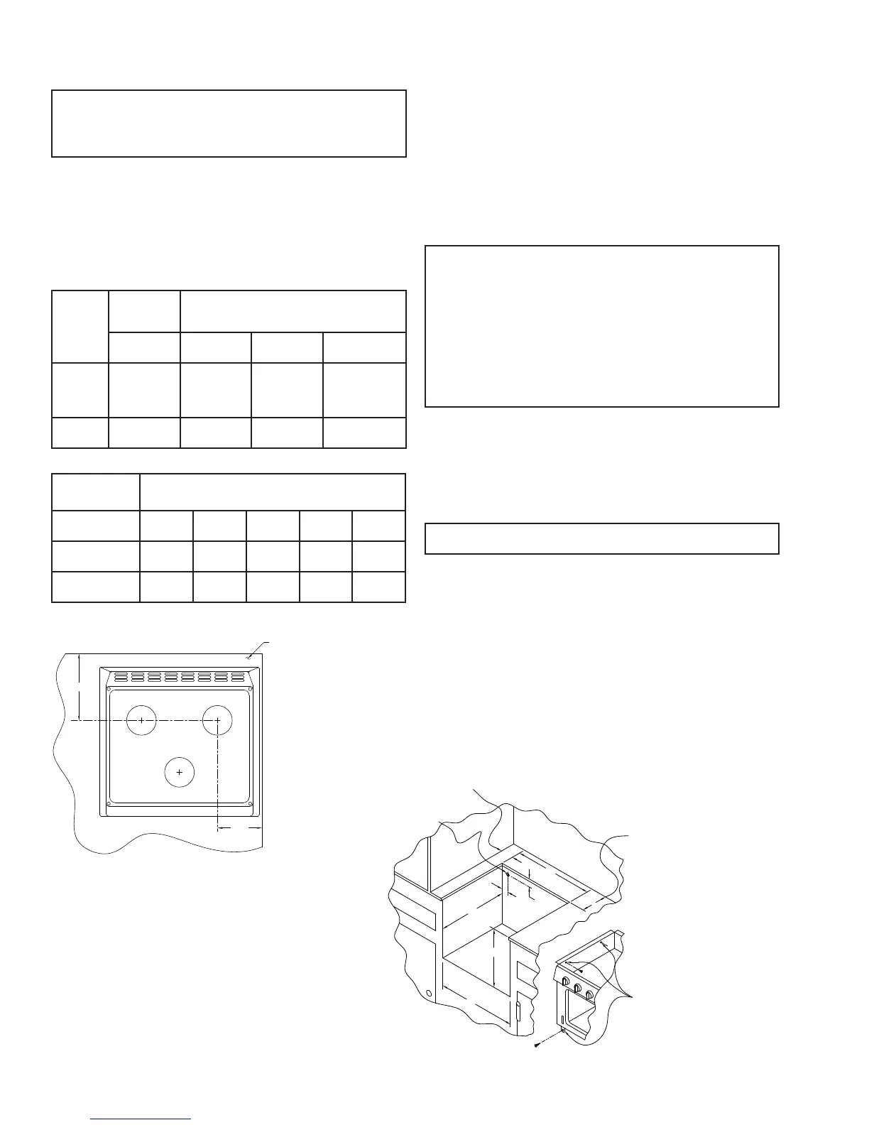
Minimum clearances from combustible walls above and below counter: (See
Figure 1A)
Models
Below
Counter
Center of Burner Head(s) to adjacent vertical
combustible material above the cooking surface
burners.
Sides, Rear
and Bottom
Right Sidewall Left Sidewall Backwall
SCN3/
SCNA3
SCS3/
SCSA3
0” 6” 6” 9”
SRNA3
SRSA3
0” 6” 6” 9”
3. Cut-out dimensions illustrated in Figure 2 are as follows:
Models
Dimensions
A B C D E
SRNA3S
SRSA3S
18 5/8” 16” 2” 20 5/8” 7/8”
SRNA3L
SRSA3L
18 5/8” 21 3/4” 2” 20 5/8” 7/8”
SCN3/SCNA3
SCS3/SCSA3
18 5/8” 3 5/8” 2” 20 5/8” 7/8”
The minimum vertical distance to combustible material above the range cooking
top is 24 inches, provided the overhead construction does not extend 13 inches
from the rear wall.
NOTE: UL and cUL certied with a minimum top clearance of 19 1/2” to overhead
combustible construction when installed with a range hood spaced a minimum of
1/4” from the construction.
4. Ensure the cabinets are properly constructed. The cabinets must be squared
with respect to the counter top and the cabinet face. For proper operation of these
units, the cabinet must be level and the bottom of the range must be supported.
After the cabinet has been prepared per the dimensions given and the gas
connection is in place, remove main top and position the unit in the cabinet
opening.
NOTE: Be sure all opening in the cabinetry around the gas lines are sealed at the
time of installation.
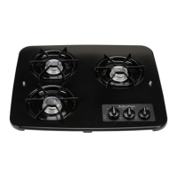
6. Fasten unit in place with wood screws through holes provided in side anges of
burner box and front frame bottom tabs with a minimum of six screws.
7. Be sure burner knobs are in “off” position. Secure gas connection and turn on
gas supply. Check all connections for leaks using soapy-water solution or a non-
corrosive leak detection solution. Do not use a soapy-water solution containing
ammonia.
NOTE: The appliance must be disconnected from the gas supply piping system
during any pressure testing of that system at test pressure in excess of 1/2 PSIG.
8. Replace main top.
9. Your unit is now ready for operation. Before operating, read the safety
information and operating instructions contained in the installation manual.
9.000
BACK WALL
SIDE WALL
6.000
C
L
OF BURNER
OF BURNER
C
L
MOUNTING SURFACE (COUNTER TOP)
SURFACE DE MONTAGE (PLAN DE TRAVAIL)
MUR LATERAL
MUR ARRIERE
DU BRULEUR
DU BRULEUR
1 3/4"
2 1/8"
D
B
D
C
E
A
GAS SERVICE PIPE OPENING
MIN. DIM. TO EITHER SIDE WALL
MIN. DIM. TO BACK WALL
MOUNTING HOLES
DÉGAGEMENT DE SÈCURITÈ - MUR LATÈRAL (2 COTÈS)
TROU POUR CANALISATION DE GAZ
DÉGAGEMENT DE SÉCURITÉ - MUR ARRIÈRE
TROUS DE MONTAGE