4
Figure 8
Figure 7
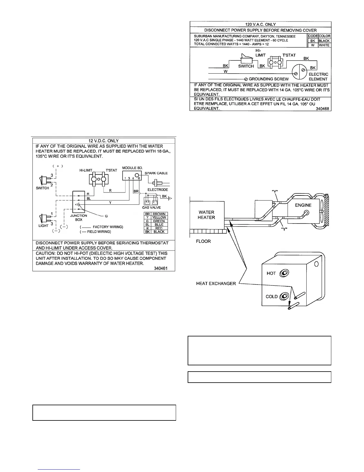
Figure 9
MAKING ELECTRICAL CONNECTIONS
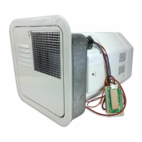
12 VOLTS D.C.
A. Applicable to following models: SW12D, SW16D, SW12DE, SW16DE,
SW12DEM and SW16DEM.
B. Refer to Figure 2 for location of D.C. junction box on models SW12D,
SW 16D, SW 12DE and SW 16DE. Refer to Figure 5 for location of D.C. junction
box on modelSW 12DEM or SW16DEM.
C. The electrical connections must be made in accordance with local codes and
regulations. In the absence of local codes and regulations, refer to the latest
edition of the National Electrical Code ANSI\NFPA No. 70.
In Canada, the electrical installation should conform with CSA standard CSA
C22.2 No. 148/Z240.6.2 Electrical Requirements for Recreational Vehicles and
CSA C22.1 Canadian Electrical Code Part 1 when installing the unit in
recreational vehicles and mobile homes respectively.
D. Make the 12 Volt D.C. electrical connections following the wiring diagram
illustrated in Figure 7.
If the power supply is to be from a convertor, we recommend that the converter
system be wired in parallel with the battery. This will serve two purposes:
1. Provide a constant voltage supply
2. Filter any A.C. spikes or volt surges
W e recommend insulated terminals be used for all electrical connections.
MAKING ELECTRICAL CONNECTIONS
120 VOLTS A.C.
A. Applicable to following models SW 12DE, SW 16DE, SW 12DEM and
SW16DEM.
B. Refer to Figure 2 for location of A.C. junction box on models SW 12DE or
SW 16DE. Refer to Figure 5 for A.C. junction box on models SW 12DEM or
SW16DEM.
C. The electrical connections must be made in accordance with local codes and
regulations. In the absence of local codes and regulations, refer to the latest
edition of the National Electrical Code ANSI/NFPA No. 70.
In Canada, the electrical installation should conform with CSA standard CSA
C22.2 No. 148/Z240.6.2. Electrical requirements for Recreational Vehicles and
CSA C22.1 Canadian Electrical Code Part 1 when installing the unit in
recreational vehicles and mobile homes respectively.
D. Check rating plate and wiring diagram (Figure 8) before proceeding. Install
a fused safety switch or circuit breaker of adequate capacity between heater
and electrical power source. Attach the black and white wires from the fused
switch or breaker to corresponding colored wires in heater junction box. A green
wire from a well grounded source must be attached to the green nut in the
junction box.
CAUTION: Before applying the 120 VAC power to the water heater junction
box, be sure the switch for electric element is in the “OFF” position.
WARNING! Before the switch for the electric element is turned to the “ON”
position, the water heater tank m ust be filled with water. See “Safety
Warnings”.
INSTALLATION OF MOTOR AID HEAT EXCHANGER
A. Place copper “Y”s in heater as shown in Figure 9.
B. Secure hoses to “Y”s with hose clamps.
C. Attach hose from motor-aid heat exchanger to “Y”s.
D. Secure hoses to motor-aid and “Y”s with clamps.
E. Check all connections for water leaks and proper water circulation through
motor-aid heat exchanger, with engine running.
The system should be checked annually for deterioration of heater hose and
hose connections. Replace as needed.
MAINTENANCE
WARNING! If the user of this appliance fails to maintain it in the condition
in which it was shipped from the factory or if the appliance is not used
solely for its intended purpose or if appliance is not maintained in
accordance with the instructions in this manual, then the risk of a fire
and/or the production of carbon monoxide exists which can cause
personal injury, property damage or loss of life.
WARNING: For your safety, all repairs should be performed by your dealer
or a qualified service person.
A. Main Burner: Do not allow the burner to burn with a yellow flame, because
sooting will occur. (See Safety W arnings).
If the burner flame is yellow and has an erratic pattern, shut unit down and contact
a qualified service agency. Do not continue operating unit with improper burner
flame. (See Figure 10 for correct and incorrect burner flame appearance.)
 Loading...