8
PARTS ILLUSTRATION AND REPLACEMENT PARTS LIST
Only factory authorized parts are to be used. Do not attempt to repair
defective parts.
W hen ordering repair parts from your dealer or a distributor, always give the
following information:
1. Part Number (Not Item No.)
2. Part Description
3. Model No. and Serial No. of your Heater
4. Number of Parts Required
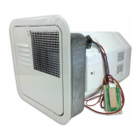
PARTS LIST FOR MODELS
SW12D and SW12DE
SW16D and SW16DE
(Figure 14)
Item Part Number
No. Description SW12D SW12DE
SW16D SW162DE
1 Foam Jacket Assy. Complete SW12D, SW12DE . . . . . . . . . . . . . . . . . . . . . . . . . . . 520960 520960
Foam Jacket Assy. Complete SW16D, SW16DE . . . . . . . . . . . . . . . . . . . . . . . . . . . 520961 520961
2 Switch, Lamp and Plate Assembly ..................................... 232589 232589
3 Module Board ...................................................... 520814 520814
5 Cover Module Board................................................. 090487 090487
6 Bushing, Snap 1/2".................................................. 070270 070270
7 Bushing, Strain Relief 5/8" ............................................ 230216 230216
8 Nut 10-24 Keps (Green) .............................................. 121576 121576
9 Bushing, Snap 7/8".................................................. ------ 230218
11 Cover, Junction Box ................................................. ------ 090576
12 D.C. Junction Box Assembly .......................................... 090517 090517
15 Flue Collector Back Assembly Complete . . . . . . . . . . . . . . . . . . . . . . . . . . . . . . . . . 101777 101777
17 Screw 10 x 1/4 (3 Required)........................................... 121577 121577
18 Valve, Pressure Relief ............................................... 161157 161157
20 Gasket, Thermostat Cover ............................................ 070987 070987
21 Cover, Thermostat/Hi-Limit............................................ 090562 090562
23 Bracket, Electrode Mounting .......................................... 063187 063187
24 Grommet.......................................................... 070874 070874
2 5 E l ec t r o d e ......................................................... 232258 232258
27 Burner Assembly with orifice .......................................... 010843 010843
29 1/4 Loxit Nut (Manifold to Valve) ....................................... 171463 171463
31 Cover, Element..................................................... ---------- 090445
32 Gasket Element Cover ............................................... ---------- 070988
33 Bushing, Snap 1/2".................................................. ---------- 070270
34 Anode ............................................................ 232767 232767
35 Grommet, Gas Inlet ................................................. 070989 070989
36 A.C. Junction Box Assembly........................................... ---------- 090575
37 Switch Assembly 120 V.A.C. T-Stat/Hi-Limit . . . . . . . . . . . . . . . . . . . . . . . . . . . . . . ---------- 232306
38 Switch Assembly 12 V.D.C. T-Stat/Hi-Limit . . . . . . . . . . . . . . . . . . . . . . . . . . . . . . . 232282 232282
40 Grommet.......................................................... 071246 071246
42 Switch, Electric Element .............................................. ---------- 232362
44 Gas Fitting ........................................................ 170374 170374
45 Electric Element with Gasket .......................................... ---------- 520900
46 Valve, Gas (LP) .................................................... 161109 161109
47 Manifold Outlet ..................................................... 171420 171420
48 Valve Mounting Bracket .............................................. 063243 063243
49 Screw 8-32 x 3/8 Hex HD (2 Required) .................................. 121958 121958
51 Burner Bracket ..................................................... 063444 063444
52 Screw 8mm - 4.0 x 1/2 Hex Washer Head (2 Required) . . . . . . . . . . . . . . . . . . . . . 121943 121943
53 1/4 Loxit Nut (Manifold to Burner) ...................................... 171463 171463
54 Electrode Wire (Not Shown)........................................... 232459 232459
55 Screw 10 x 1/4 (No Substitute) (2 Required) . . . . . . . . . . . . . . . . . . . . . . . . . . . . . . 121577 121577
 Loading...