7
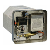
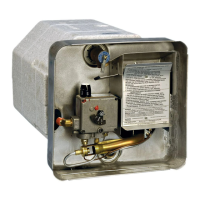
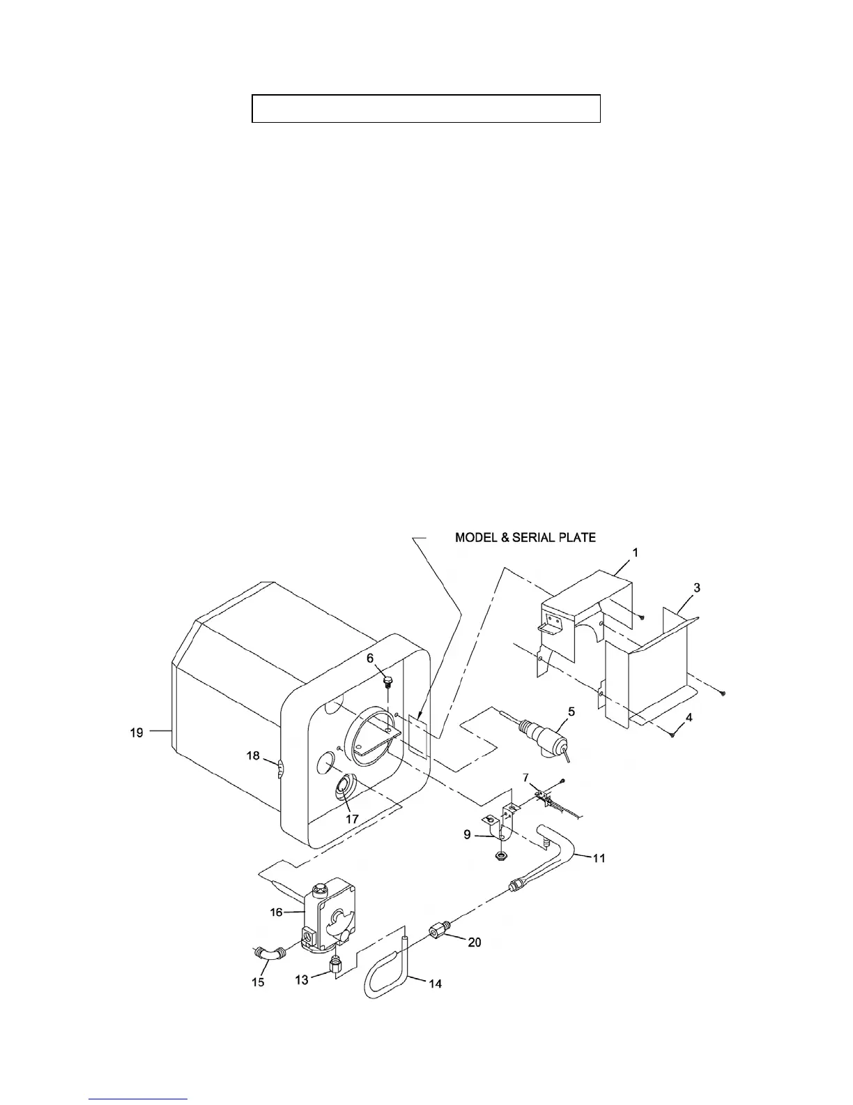
Figure 9
PARTS ILLUSTRATION AND REPLACEMENT PARTS LIST
Only factory authorized parts are to be used. Do not attempt to repair
defective parts.
W hen ordering repair parts from your dealer or a distributor, always give the
following information:
1. Part Number (Not Item No.)
2. Part Description
3. Model No. And Serial No. of your Heater
4. Number of parts Required
Item Part
No. Description Number
1 Back Assembly Flue Collector...................................... 101682
3 Front, Flue Collector ............................................. 101683
4 Screw 10 x 1/4 .................................................. 121577
5 Valve, Pressure Relief ............................................ 161157
6 Screw 8mm - 4.0 x 1/2 Hex W asher Head (2 Required)) . . . . . . . . . . . . . . . . . 121943
7 Pilot Burner/Thermocouple ........................................ 161156
9 Burner Bracket ................................................. 063444
11 Burner with Orifice ............................................... 010844
13 1/4 Loxit Nut (Manifold to Valve) .................................... 171463
14 Manifold Outlet.................................................. 171421
15 Elbow ......................................................... 171394
16 Thermostat/Valve (SIT) ........................................... 161111
17 Anode ........................................................ 232767
18 Grommet, Gas Inlet .............................................. 070989
19 Foam Jacket Assembly Complete ................................... 520 867
20 1/4 Loxit Nut (Manifold to Burner) ................................... 171463
 Loading...