Section 4
COMPRES SOR SYSTEMS
9
4.1 INTRODUCTION
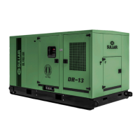
Your Sullair DR---13, rotary screw air compressor
will provide you with improved reliability and re-
duced maintenance.
Read Section 7 (Maintenance) to keep your com-
pressor in top operating condition. Should any
questions arise which cannot be answered in the
following text, call your nearest Sullair office or the
Sullair Corporation Service Department.
I M P O R TA N T --- Yo u r D R --- 1 3 c o m p r e s s o r p a c k a g e
utilizes a simple to operate yet sophisticated com-
puterized controller identified throughout this doc-
ument as the Supervisor II. All pertinent use of this
device is covered herein. Carefully familiarize your-
self with it before attempting to operate the machin-
ery.
4.2 DESCRIPTION OF COMPONENTS
Refer to Figure 4---1. The standard package in-
cludes a two -- stage compressor and gear box
assembly,anelectric motor and driveline sys-
tem,aSupervisor II co ntrol assembly,aninlet
air system, low pressure (LP) and high pressure
(HP) silencing/discharge air systems, air cool-
ing system,aload/unload control system,anoil
lubrication and cooling system,andasound at-
tenuating enclosure, all mounted on a fabricated
steel frame.
Air---cooled heat exchangers are used on all mod-
els. A motor driven fan is used t o ventilate the interi-
or of the sound attenuating enclosure. The Super-
visor II assembly is easily accessible for servicing
behind a hinged and locked separate enclosure
panel door.
4.3 COMPRESSOR UNIT, FUNCTIONAL DESCRIP-
TION
S u l l a i r D R --- 1 3 c o m p r e s s or s f e a t u r e a t w o --- s t a g e ,
oil free, rotary screw design. The rotor profiles and
stators, which are protected w ith anti---corrosion
coatings, deliver near pulse---free compressed air
to meet your demands. The rotor shafts are
mounted on anti--- friction bearings and are sealed
by floating carbon ring/stainless steel cage assem-
blies. Both stages are driven by a common bull
gear and speed optimized individual pinions, and
are precisely mounted to the rigid gear box. Timing
gears synchronize each male/female rotor pair for
contact---free operation. Variations of compressor
speed, and ultimately flow capacity, are deter-
mined by the ratio of pinions--- to---bull gear set
CHECK VALVE
HIGH PRESSURE
SILENCER
CONTROL
CYLINDER
HIGH PRESSURE
COOLING FAN
MOTOR
AIR
FILTER
COMPRESSOR
UNIT MOTOR
AIR INLET
VALVE
THERMAL
VALVE
LOW PRESSURE
COMPRESSOR UNIT
OIL SUMP
TANK
COMPRESSOR UNIT
Figure 4 ---1 Description of Components (Typical)

 Loading...