EasyManua.ls Logo

Sullair 900XH - User Manual

Sullair 900XH
142 pages
To Next Page IconTo Next Page
Loading...
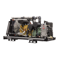
OPEN FRAME
AIR COMPRESSOR
900XH - 1350XH
and Aftercooled Models
350 PSIG
CATERPILLAR
OPERATOR’S
MANUAL AND
PARTS LIST
KEEP FOR
FUTURE
REFERENCE
Part Number
02250166-434
©Sullair Corporation
The information in this document is
correct at the time of printing for
Portable Compressor Serial Number
200601080007
and all subsequent Serial Numbers.

Table of Contents

Questions and Answers:

Sullair 900XH Specifications

General IconGeneral
BrandSullair
Model900XH
CategoryAir Compressor
LanguageEnglish

Summary

Section 1 Safety

1.1 General Safety Precautions

General safety guidelines for operating and maintaining Sullair equipment.

1.2 Towing Safety Procedures

Detailed instructions for safely towing the air compressor unit.

1.3 Pressure Release Procedures

Steps for safely releasing pressure and installing flow-limiting valves.

1.4 Fire and Explosion Hazards

Precautions to prevent fire and explosion risks during operation and refueling.

1.5 Moving Parts Safety

Guidelines to avoid injury from moving parts like belts and fans.

1.6 Hot Surfaces, Sharp Edges

Warnings about contact with hot surfaces and sharp edges on the compressor.

1.7 Toxic and Irritating Substances

Information on handling toxic substances and ensuring safe air quality.

1.8 Electrical Shock Prevention

Safety measures to prevent electrical shock hazards.

1.9 Lifting Procedures

Safe practices for lifting and suspending the compressor unit.

1.10 Entrapment Hazards

Precautions to prevent personnel entrapment within the compressor enclosure.

1.11 Jump Starting Procedures

Safe methods for jump-starting the compressor's engine.

Section 2 Description

2.1 Introduction to Compressor Models

Overview of Sullair 900XH-1350XH Open Frame Air Compressor features.

2.2 Description of Components

Identification and overview of the main components of the compressor unit.

2.3 Sullair Compressor Unit Function

Functional description of the Sullair two-stage, flood-lubricated compressor.

2.4 Compressor Cooling & Lubrication System

Functional description of the system maintaining compressor temperature and lubrication.

2.5 Compressor Discharge System

Functional description of the system that processes compressed air/fluid mixture.

2.6 Capacity Control System

Functional description of the system regulating air intake based on demand.

2.7 Air Inlet System

Description of the air filters and inlet valve that control air intake.

2.8 Instrument Panel Group

Description of the EMS unit, warning lamps, and digital LCD display.

2.9 Engine Control Module Function

Explanation of Diagnostic Fault Codes and their relation to engine performance.

2.10 Electrical System Function

Description of the electrical system components and shutdown functions.

2.11 Aftercooler Air System

Description of the aftercooled system for reducing compressed air temperature.

Section 3 Specifications

3.1 Model Specifications

Technical specifications for the 900XH, 1150XH, and 1350XH models.

3.2 Compressor Lubrication Guide

Fluid types, change periods, and ambient temperature ranges for compressor lubrication.

3.3 Application Guide for Fluids

Guidance on using Sullair AWF and other motor oils, and fluid condition checks.

3.4 Engine Lubrication Guide

Reference to the Engine Operator's Manual for engine oil specifications.

Section 4 Operation

4.1 General Operation Overview

Introduction to compressor operation, controls, and indicators.

4.2 Purpose of Controls and Indicators

Explanation of the function of each control and indicator on the compressor.

4.3 Initial Start-Up Procedure

Step-by-step guide for the first-time start-up of the compressor.

4.4 Subsequent Start-Up Procedure

Procedure for starting the compressor after initial start-up.

4.5 Shutdown Procedure

Instructions for safely shutting down the compressor.

Section 5 Maintenance

5.1 General Maintenance Program

Overview of the maintenance program for long compressor life and engine requirements.

5.2 Daily Operation Checks

Essential checks to perform daily before starting the compressor.

5.3 Maintenance After Initial 50 Hours

Initial maintenance tasks to prevent unnecessary problems after 50 hours.

5.4 Maintenance Every 100 Hours

Tasks required for maintenance every 100 hours of operation.

5.5 Maintenance Every 250 Hours

Maintenance procedures to be performed every 250 hours.

5.6 Maintenance Every 300 Hours

Maintenance tasks, including fluid and filter changes, every 300 hours.

5.7 Maintenance Every 500 Hours

Required maintenance every 500 hours, including fluid and filter replacement.

5.8 Maintenance Every 1000 Hours

Maintenance tasks to be performed every 1000 hours of operation.

5.9 Parts Replacement & Adjustment

Procedures for compressor fluid change and servicing the main fluid filter.

5.10 Troubleshooting Guide

Troubleshooting chart based on factory tests and common issues.

5.11 Troubleshooting Guide Details

Detailed troubleshooting guide for common compressor symptoms and causes.

Section 6 Noise Control

6.1 Noise Emissions Warranty

Details of the warranty covering noise emissions compliance.

6.2 Tampering with Noise Control System

Prohibition against tampering with noise control devices and systems.

6.3 Noise Emissions Maintenance Record

Instructions and log for maintaining noise emission levels.

Section 7 Illustrations and Parts

7.1 Procedure for Ordering Parts

Instructions on how to order replacement parts from Sullair representatives.

7.2 Recommended Spare Parts List

List of recommended spare parts, including elements and repair kits.

7.3 Engine and Compressor Mounting

Diagrams and part numbers for engine and compressor mounting components.

7.4 Air Inlet System - All Models

Illustrations and part numbers for the air inlet system components.

7.5 Exhaust System - All Models

Diagrams and part numbers for the exhaust system components.

7.6 A Engine Radiator and Fluid Cooling System

Illustration and parts list for the engine cooling system (standard models).

7.6 B Engine Radiator and Fluid Cooling System - Aftercooled

Illustration and parts list for the engine cooling system (aftercooled models).

7.7 Engine Radiator Assembly - All Models

Exploded view and parts for the engine radiator assembly.

7.8 Aftercooler Mounting - All Models

Diagrams and part numbers for mounting the aftercooler assembly.

7.9 Control System Hose Routing

Diagram showing the routing of hoses for the control system.

7.10 Speed Control Cylinder and Parts

Illustration and part numbers for the speed control cylinder assembly.

7.11 Air Control Manifold Assembly

Diagram and part numbers for the air control manifold assembly.

7.12 A Inlet Valve and Parts (6.5) - 900 XH

Illustration and parts list for the 6.5" inlet valve assembly.

7.12 B Inlet Valve and Parts (8) - 1150 XH and 1350 XH

Illustration and parts list for the 8" inlet valve assembly.

7.13 A Inlet Valve Parts - 6.5 - 900 XH

Detailed breakdown of parts for the 6.5" inlet valve.

7.13 B Inlet Valve Parts - 8 - 1150 XH and 1350 XH

Detailed breakdown of parts for the 8" inlet valve assembly.

7.14 A Discharge System - 900 XH and 1150 XH

Illustration and part numbers for the discharge system.

7.14 B Discharge System - 900 XH-1150 XH Aftercooled

Illustration and part numbers for the aftercooled discharge system.

7.14 C Discharge System - 1350 XH Aftercooled

Illustration and part numbers for the 1350XH aftercooled discharge system.

7.15 A Receiver and Parts - 900 XH & 1150 XH

Illustration and part numbers for the receiver and parts assembly.

7.15 B Receiver and Parts - 1350 XH

Illustration and part numbers for the 1350XH receiver and parts assembly.

7.16 Water Separator Trap - Aftercooled Only

Illustration and part numbers for the water separator trap.

7.17 Sub-Assembly - High Pressure Filter; Check Valve; Orifice

Illustration and part numbers for the high pressure filter/check valve/orifice sub-assembly.

7.18 Discharge; Check Valve Assembly

Illustration and part numbers for the discharge/check valve assembly.

7.19 Minimum Pressure; Check Valve

Illustration and part numbers for the minimum pressure/check valve.

7.20 Fuel System and Parts - All Models

Illustration and part numbers for the fuel system components.

7.21 Electrical Parts - All Models

Illustration and part numbers for the electrical system components.

7.22 Instrument Panel and Parts

Illustration and part numbers for the instrument panel and its components.

7.23 Frame and Parts

Illustration and part numbers for the compressor frame and associated parts.

7.24 Decal Group

Illustrations showing the location and types of decals on the compressor.

7.25 Decal Locations

Diagrams indicating the placement of various decals on the compressor unit.

Related product manuals