22
6–1) Attaching/Detaching The Terminal Box Cover
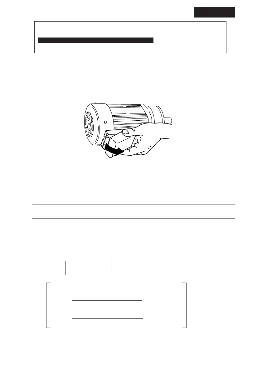
(1) Detaching
As shown in Fig. 27, hold both sides of the terminal box and pull it towards you. The cover
will detach.
(2) Attaching
Press the terminal box cover to the terminal box case until it snaps into place.
Fig.27
6–2) Measuring Insulation Resistance
· When measuring the insulation resistance, disconnect the motor from the control panel.
Check the motor separately.
Measure the insulation resistance before wiring. The insulation resistance (R) varies according to
the motor output, voltage, type of insulation, coil temperature, humidity, dirt, period of operation,
test electrification time, etc. Usually, the insulation resistance exceeds the values shown in Table
6.
Megohmmeter voltage
Insulation resistance
(R)
500V
1M(Ω) or more
Table 6 Insulation resistance
Reference: The following equations are shown in JEC–2100.
R (> or =)
Rated voltaga (V)
Rated voltaga (V) + Speed (rpm)/3
Rated output (kW) + 2000
Rated output (kW)+1000
R (> or =)
+ 0.5 (
MΩ
)
(
MΩ
)
A drop in insulation resistance may be attributed to poor insulation. In that case, do not turn on the
power. Contact our nearest agent, distributor, or sales office.
COMMON
· Long cables cause voltage to drop. Select cables with appropriate diameter so that
the voltage drop will be less than 2%.
·
After wiring outdoor and explosion-proof type motors , check that terminal box
mounting bolts are not loose, and correctly attach the terminal box cover.
6. Wiring
 Loading...