31
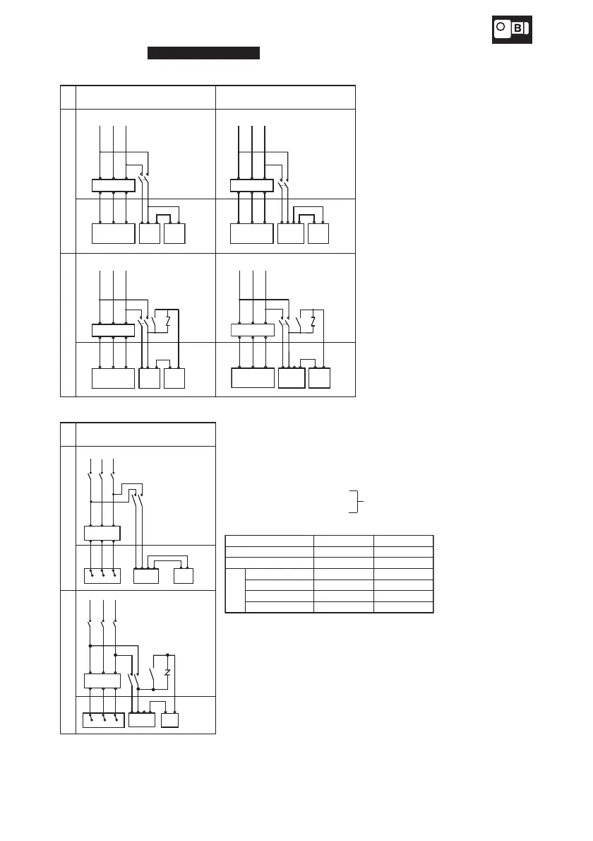
Fig.31 shows the Inverter motor with brake connection and the standard specifications for terminal codes.
Fig.31-a For inverter driven (In a case of three lead wires)
Braketype:
FB-02A1-05A1
Braketype:FB-1D-10B1
RS
T
MC
UVW
12 4
MN
Rectifier
Brake
Motor
Inverter
RS
T
RS
T
MC
UVW
1234
MN
Rectifier
Brake
Motor
Inverter
Rectifier
Brake
Motor
Inverter
RS
T
UVW
12 4
MN
VR
MC
RS
T
RS
T
UVW
1234
MN
VR
MC
Rectifier
Brake
Motor
Inverter
Fig.31-b For inverter driven (In a case of six lead wires)
Brake type : FB-15B1
U1
V1 W1
1234
MN
V2
W2
U2
T
MC
R
S
MCB
Rectifier
Brake
Motor
Inverter
1423
MN
R
S
T
VR
MC
MCB
U1
V1 W1
V2
W2
U2
Rectifier BrakeMotor
Inverter
Nomal braking action
Fast braking action
Control panel
Terminal box
Control panel
Terminal box
Control panel
Terminal box
Control panel
Terminal box
Nomal braking action
Fast braking action
Control panel
Terminal box
Control panel
Terminal
box
MC : Electromagnetic contactor
VR : Varistor (Protector element)
These should be furnished
by the customer.
Varistor (VR) Capacity
Input power AC200V–230V AC380V–460V
Rated voltage of varistor AC260V–300V AC510V
Voltage of varistor 430V–470V 820V
Rated power
of varistor
FB-02A1,05A1
0.25Watt or more
0.4Watt or more
FB-1D 0.4Watt or more 0.6Watt or more
FB-2D, 3D, 5B, 8B 0.6Watt or more 1.0Watt or more
FB-10B1,15B1 1.0Watt or more 1.0Watt or more
Varistor is optionally available at Sumitomo.
Use fast braking action for lifting devices or for better stopping accuracy.
DC braking capacity (for DC coil loading) exceeding 5 times the braking current
shown on the name plate is recommended for the fast braking action.
· Refer to page 6 table 1-2 for brake type.
·
For Three-Phase Motors and Three-Phase High Efficiency Motor to be driven by Inverters, please refer to the wiring diagram for inverter motor.
· Insulation suitable for a motor is necessary in inverter drive with 3-phase 400V motor or 3-phase 400V high efficiency motor.
· Inverter can not be applied to MB brake type (excl. water-proof type) due to a built-in rectifier into brake.
·
This drawing shows for a motor based on standard specification for domestic market. Motor based on overseas standard shall be referred to us.
· Refer to connection diagram on the motor when sharing power supply.
6. Wiring