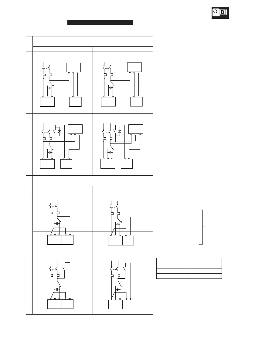
Nomal braking action
Fast braking action
Control panel
Terminal box
Control panel
Terminal box
Control panel
Terminal box
Control panel
Terminal box
Nomal braking action
Fast braking action
Control panel
Terminal box
Control panel
Terminal box
Control panel
Terminal box
Control panel
Terminal box
●
Use fast braking action for lifting devices or
for better stopping accuracy.
●
DC braking capacity (for DC coil loading)
exceeding 5 times the braking current shown
on the name plate is recommended for the
fast braking action.
Note 1: A rectifier is supplied separately for SB-
004.
Note 2: A rectifier is built in the brake of motors
for MB-003-MB005. (A rectifier is
supplied separately for water-proof
type.)
Note 3: Turn the switch SW to change the
current of 15-90W motors to the
opposite direction. (When instant
switching is required, use a reversible
motor.)
Note 4: Do not open water-proof dust-proof box
for water-proof type, otherwise
electrical shock, fire or damage to the
equipment may result.
Note 5: Rectifier, capacitor are not water-
proofed for water-proof type.
Note 6: Connect the accessory capacitor.
MC : Electromagnetic
contactor
OLR : Overload relay or
thermal relay
SW : Rotation shifting switch
VR : Varistor (Protector
element)
C : Capacitor (Accesorry)
These should
be furnished by
the customer.
· Refer to page 6 table 1-1 for brake type.
· This drawing shows for a motor based on standard specification for domestic market. Motor
based on overseas standard shall be referred to us.
 Loading...