30
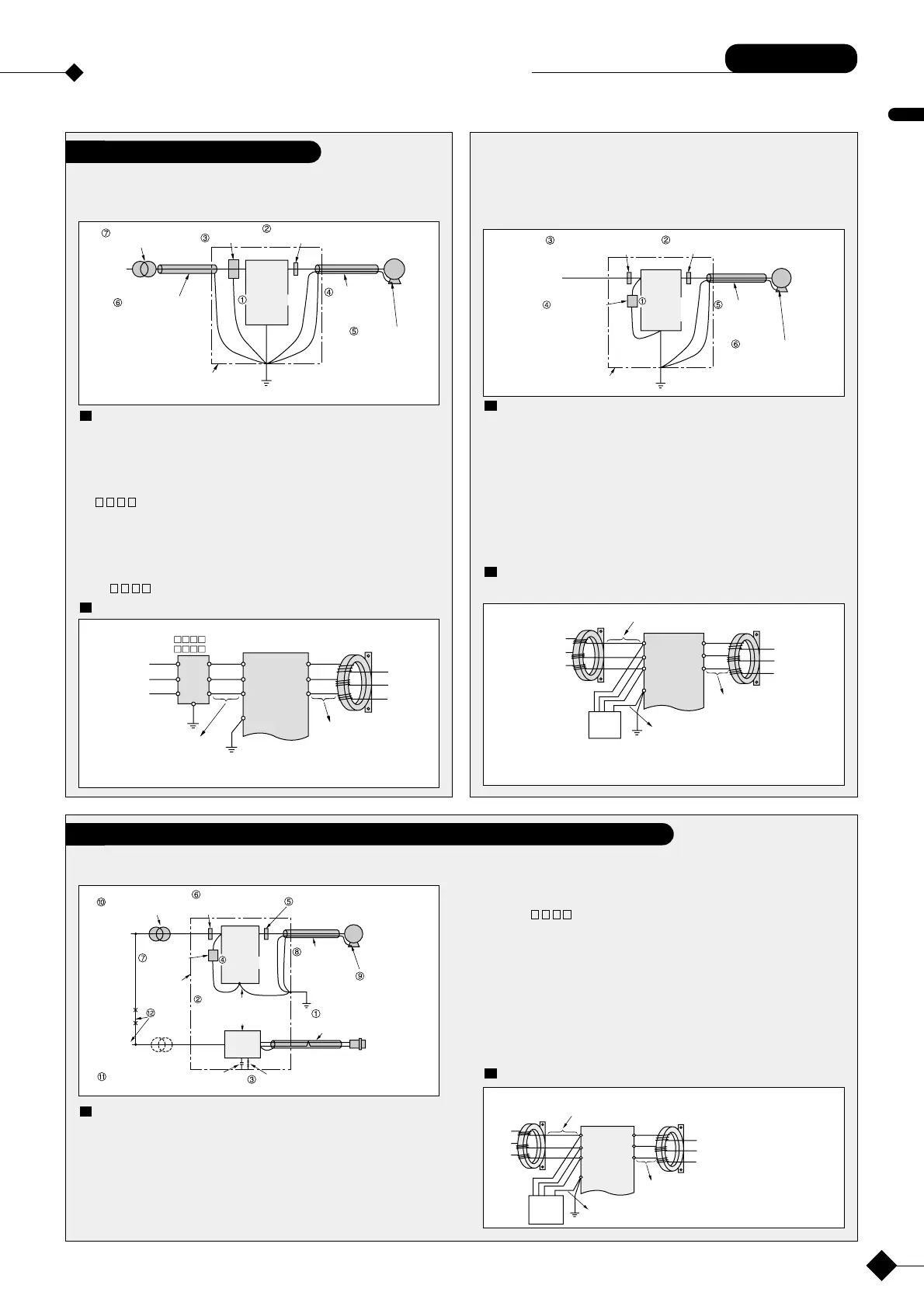
Example of noise filter use
Example of noise filter use
Common
1. When noise level is high
Take possible measures among the following in the order of q–u.
Each measure will improve noise reduction.
Insulated transformer or
noise-cut transformer
Zero-phase reactor
3-times winding (4 T) or more
lower the carrier
frequency.
Metal conduit or
shielded cable
grounded at
one point
Use 4-wire cable
as a motor power
line, and ground
one of the wires.
Note: The above measures may be
insufficient in places where the
broadcast reception is weak.
Metal tube or shielded
cable grounded at one
point
LC filter
Inverter
Power
supply
Control panel or machine frame
R
S
T
U
V
W
E
IM
Make the cable as
short as possible.
Motor
Zero-phase reactor
RC5078
U
V
W
R
S
T
E
Inverter
–CD
–FS
NF3
HF3
1
2
3
4
5
6
Control panel or machine frame
Power
supply
LC filter
Note: Turn wires the same number of times for all phases of the zero-phase
reactor. 3 times (4 T) or more Increase the number of zero-phase reactor
when the cable is too thick to wind correctly.
2. When noise level is low
Take possible measures among the following in the order of q–y.
Each measure will improve noise reduction.
Corrective measures
qLower the carrier trequency as much as possible. Up to approx. 10 kHz
when low-noise operaton is necessary.
wInstall a zero-phase reactor on the output side of the inverter.
(Type: RC5078, RC9129)
eInstall a zero-phase reactor on the input side the inverter.
(Type: RC5078, RC9129)
rInstall a capacitive filter on the input side of the inverter.
(Type: 3XYHB-105104)
tConnect the inverter and motor with a metal conduit or shielded cable.
yUse 4-wire cable as a motor power line, and ground one of the wires.
Connection of we zero-phase reactor and r capacitive
filter
Lower the carier
frequency as much
as possible.
Power
supply
Control panel or machine frame
R
S
T
U
V
W
E
Inverter
IM
Zero-phase reactor
3-times winding (4 T) or more
Zero-phase reactor
3-times winding (4 T) or more
Metal conduit or
shielded cable
grounded at
one point
Use 4-wire cable
as a motor power line,
and ground one of the
wires.
Capacitive filter
Make the cable as
shortas possible.
Make the cable as short as possible.
Make the cable as short
as possible.
Power
supply
Power
supply
(Note)
Zero-phase reactor
RC5078
Zero-phase reactor
RC5078
U
V
W
R
S
T
E
Inverter
Capacitive
filter
3XYHB
-105104
Black
Black
Black
Blue/
Green
Note: Turn wires the same number of times for all phases of the zero-phase
reactor. 3 times (4 T) or more Increase the number of zero-phase reactor
when the cable is too thick to wind correctly.
Take possible measures among the following in the order of q–!2.
Each measure will improve noise reduction.
Corrective measures
qUse twisted pair/shielded wire as a sensor signal line, and connect the
shielded wire to common.
wSeparate the inverter and power line from the sensor circuit as much as
possible. (More than 10 cm desirable)
eRemove the grounding wire when the power supply for the sensor is
grounded.
rLower the carrier frequency as much as possible. Up to approx. 10 kHz
Ground this part via a 0.01-0.1 µF
capacitor instead of direct grounding
Drive isolation or noise
reduction transformer
Zero-phase reactor
3-times winding (4 T)
or more
Zero-phase reactor
3-times winding (4 T)
or more
Lower the carrier
frequency as much
as possible
Metal conduit
orshielded
cablegrounded
atone point
Use 4-wire cable as
a motor power line,
and ground one of
the wires.
Use twisted bare/shielded wire.
Connect the shielded wire to the
common signal.
Avoid direct grounding
Power
supply
R
S
T
U
V
W
E
Inverter
IM
Sensor
DC power
supply
for sensor
FC
+
-
Step-down transformer
Control
power supply
Capacitive
filter
Separate
the power
system
Control panel
or machine
frame
Separate the inverter and power
line from the sensor circuit
as much as possilbe.
(More than 10 cm)
when low-noise operation is necessary.
tInstall a zero-phase reactor on the output side of the inverter.
(Type: RC5078, RC9129)
yInstall an LC filter on the input side of the inverter.
(Type: FS)
uInstall a capacitive filter on the input side of the inverter.
(Type: 3XYHB-105104)
iUse a metal conduit or shielded cable for power supply wiring.
oUse 4-wire cable as a motor power line, and ground one of the wires.
!0Install a drive isolation or noise reduction transformer for the inverter
power supply.
!1Gorund the power supply for the sensor via a 0.01-0.1
→(630V 0.1µF)
!2Separate the inverter power supply from the sensor power supply system.
Connection of ty reactors and u capacitive filter
Make the cable as
short as possible.
Make the cable as
short as possible.
Make the cable as
short as possible.
Power
supply
Motor
(Note)
Zero-phase reactor
RC5078
RC9129
Zero-phase reactor
RC5078
RC9129
U
V
W
R
S
T
E
Inverter
Capacitive
filter
3XYHB
-105104
Black
Black
Black
Yellow/
Green
Note: Turn wires the same
number of times for
all phases of the
zero-phase reactior.
3 times (4 T) or
more. Increase the
number of zero-
phase reactors when
the cable is too thick
to wind correctly.
Corrective measures
qLower the carrier frequency as much as possible. Up to approx. 10 kHz
when low-noise operation is necessary.
wInstall a zero-phase reactor on the output side of the inverter.
(Type: RC9129)
eInstall an LC filter on the input side of the inverter.
( -FS)
rConnect the inverter and motor with a metal conduit or shielded cable.
tUse 4-wire cable as a motor power line, and ground one of the wires.
yConnect the inverter and power with a metal conduit or shielded cable.
uInstall a drive isolation or noise reduction transtormer for the power
supply.
differs according to the inverter capacity and voltage.
Connection of w zero-phase reactor and e LC filter
when AM radio picks up noise
Measures to take when proximity switch/photoelectric switch, etc. malfunction
 Loading...
