I T L S E R V I C E M A N U A L
H-16
HYDRAULIC SYSTEM
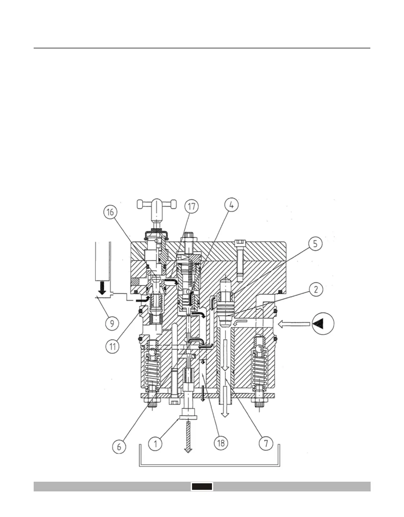
At the same time the pressure oil contained in the cylinder (chamber “9”) flows to the tank therefore causing the
lowering of arms.
By screwing the lever the lowering speed is reduced, by screwing totally the valve “16” is closed on the seat and
therefore the arms are locked for transport safety.
The oil coming from the pump enters in the annular duct “8” is able to move the differential valve “2” downward and
open the discharge hole “7” and enables the oil go to the tank.
During this phase the control valve supplies at the same time the oil coming from the pump and the oil contained in the
cylinder to the discharge causing the lowering of the arms.
In this phase the lowering speed of the implement can be adjusted with the lever AP.
The control spool “1” is in such a position to connect chamber “5” of differential valve directly to the discharge through
hole “6”.
Discharge Phase
From chamber “9” the oil goes into the annular duct “11” passing the lowering speed regulation valve “16” through the
connecting hole “17” enter into the discharge valve “4” that is kept open from the spool “1” and goes to discharge from
hole “18”.
 Loading...