I T L S E R V I C E M A N U A L
H-20
HYDRAULIC SYSTEM
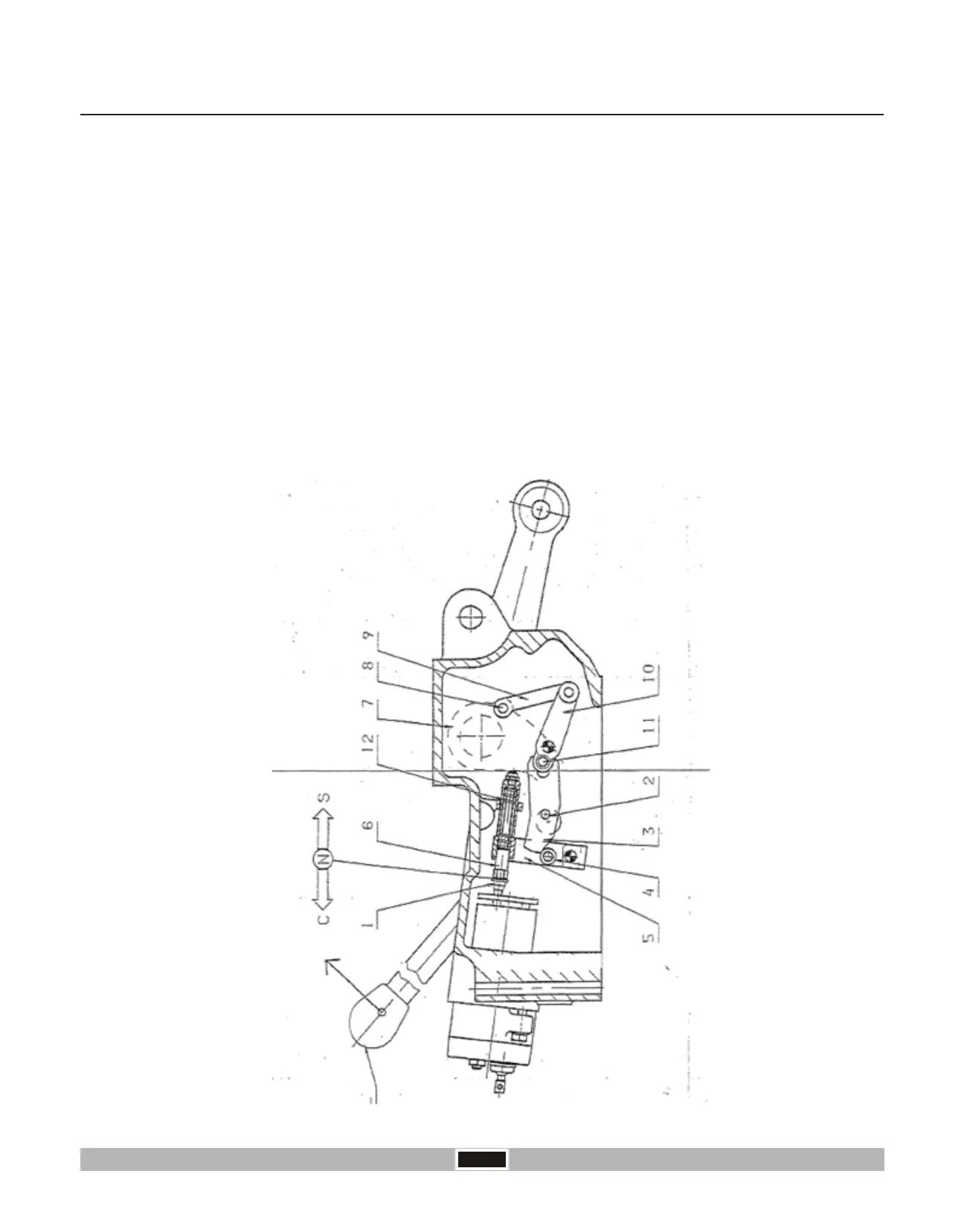
Operation of Internal Levers in Controlled Position:
The cam shaft “2”welded to lever “L” turns clockwise and rotates the cam lever “3” anticlockwise. This pushing on the
roller cam bowl “4”. Rotates anticlockwise the toggle lever “5” which due to the position of the push rod “6” moves the
shaft “1” of the control valve in delivery phase (C) which consequently raises the arms of the rockshaft.
When the arms are lowered the movement of the internal levers is in the opposite direction as described above.
Moving the control lever “L” (In the direction of the arrow) one can raise the arms and the internal levers affect the
Control Valve in the following way:-
The push rod “6” is kept in a fixed position with the toggle lever “5” by the spring seat “12”. The spring seat “12” has the
function of absorbing the extra strokes of the internal levers when lever “L” is moved from its lowest position to its
highest position and vice-versa.
With the raising movement the crank “7” with its pin “8” rotate anticlockwise and by means of lever “9” they rotate the
balance lever “10” in the same direction. The lever “10” with its roller cam bowls “11” cause a clockwise rotation of the
cam lever “3”. The roller cam bowl “4” remains in contact with the lever by the effect of springs of the shaft “1”, so the
toggle lever “5” rotates clockwise returning, by means of the push rod “6”, the Control Valve in its neutral position (N)
and blocking the raising of the arms.
 Loading...