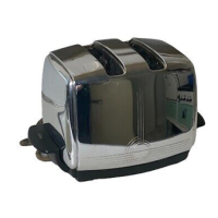
-
5
-
of the Element Assembly; the Insulator
(4)
slides off of the Bus Bar. Now the Window
End Assembly, End Top Plate, and Guide Wires can be separated. Follow the same
procedure and precautions in removing the other End Top Plate
(3)
and Closed End
Element Assembly
(6),
but first remove Hex Nut
(7)
and Washer
(8),
disconnecting Lower
Bus Bar from Center Element.
3. Release Guide Wires, then remove Screws
(2).
Lift Center Element Assembly
(10),
with
Center Top Plate attached, clear of the mechanism. Remove Screws
(18),
releasing
Lifter Lever Assembly
(19)
from mechanism, then remove Screws
(2)
freeing Frame Cross
Yoke
(15).
Remove Screws
(2),
and lift Side Frame
(14)
from Mounting Plate Assembly
and clear of Bread Lifter Assembly
(17).
Follow the same procedure for other Side
Frame. Now you can pick
up
Bread Lifter Assembly off of Mounting Plate Assembly.
Unhook Lift Lever Depression Bar
(22)
from Lift Lever Assembly, separating Lift Lever
Depression Bar from the Mounting Plate Assembly.
B. REASSEMBLY
1.
Set
Mounting Plate Assembly
(20)
on
top
of Lift Lever Depression Bar
(22)
and hook
Lift Lever Assembly
(19)
onto Lift Lever Depression Bar. Connect Switch Lead
(21)
with
Washer
(8)
and Hex Nut
(7)
onto Mounting Plate Assembly. Place Bread Lifter Assembly
(17)
on
top
of Mounting Plate Assembly.
Set
Side Frame Assemblies
(14)
and
(16)
into
place with the Bread Lifter Assembly
set
in the slots and fasten with Screws
(2).
Now
with the Bread Lifter Assembly
set
in slots of Side Frame Assemblies and Lift Lever
Assembly, fasten Frame Cross Yoke
(15)
with Screws
(2)
onto Side Frame Assembly.
2.
Set
Window End Element Assembly
(11)
and Closed End Element Assembly
(6)
into place.
Install Guide Wires
(9)
onto Center Top Plate of Center Element Assembly
(10). Set
Center Assembly into place with Upper and Lower Bus Bars of
the End
Element Assemblies
on respective terminals,
so
that Adjustment Screw is in center hole of Lift Lever
Depression Bar, and fasten Center Top Plate with Screws
(2).
Hook Guide Wires
onto
Mounting Plate Assembly.
Replace
Washer
(8)
and Nut
(7)
on Bus Bar terminals of Center
Element. Slide Insulators
(4)
onto Bus Bar of Window
End
Element. Slide Thermostat
Assembly
(12)
into place, and
connect
Upper Lead Bracket of Element Assembly and
Switch Lead Wire
(21)
onto Thermostat Assembly with Washers
(8)
and Screws
(13).
Hook
3 to
4 turns of
Carriage Counter Balance
Spring
(3A)
over Top End Plate
(3).
Hook the
looped end in
hole
in Bread Lifter Assembly (17). Fasten End
Shells
(5)
and
Center
Shell
(1)
onto
mechanism
assembly
with Screws
(2)
. Use Tool No. 2
when
fastening
Center
Shell
to
mechani
sm. After End Shells are fastened, set Center Shell in place,
then holding Toaster by the Base,
push down
into Tool
No.
2 until holes in Center
Shell are lined up
with holes
on Mounting Plate Assembly. Insert
Screws
and tighten.
Push Cord Clamp
(23)
into slot in Mounting Plate Assembly. Push terminal end of Plug
and Cord Assembly
(24)
through hole provided in Base (25) and