Page 16
680 SERIES
10. Connect wires, color to color, on terminal blocks TB1 and TB3
(Figures C-F, page 17). TIGHTEN SECURELY! All wires must be
hooked up securely or damage could result.
11. Install control box door and screws and reinstall the cabinet side
panels.
Figure A
Equipment Area
3
2
2
5
5
1
7
4
6
WARNING!
DONOT LOOK AT LIT BULB
SEVERE EYE DAMAGE
OR BLINDNESS CAN OCCUR
9
8
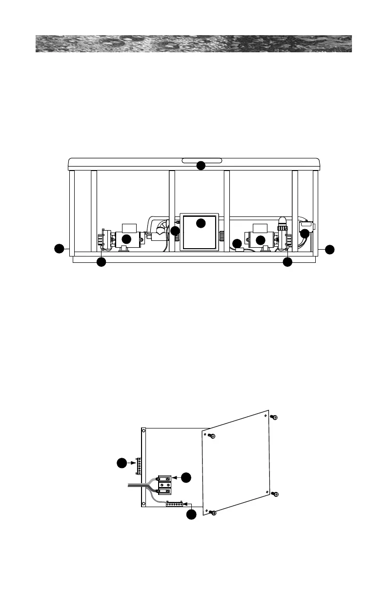
1. Control Box
2. Power Supply Inlet(s)
3. 2-Speed Pump
4. Heater
5. Pump Drain Plugs
6. 1-Speed Pump
7. Control Panel
8. CLEARRAY (Ultraviolet) Water
Purication System
9. Electronic Ballast (For the CLEARRAY
System)
Note: Equipment location (such as pumps, CLEARRAY®
system, drain, heater etc.) varies by model.
Figure B
Control Box
1. Terminal Block
2. Bonding Lug
3. Grounding Terminal








 To Next Page