Computer Battery Installation
SD-589 (19 Function)
Setting(km)/(mile)
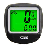
Bicycle Computer Instruction Manual V1.0
Installation of Speedometer
- SPD Current Speed
- ODO Odometer (0~99999km/m)
- DST Trip Distance
- MXS Maximum Speed
- AVS Average Speed
- TM Elapsed Time
- CLK Clock (12H/24H)
- TMP Temperature / (-10°C~70°C)
- SCAN
- “+”“-”Comparator
- SETTING TYRE CIRCUMFERENCE / (0mm~9999mm)
- SETTING SPEED SCALE (km,m)
- MAINTENANCE ALERT
- SETTING THE LAST VALUE OF ODOMETER / ODO
- COMPUTER LOW BATTERY INDICATOR
- WIRELESS WAKE UP
- AUTO BACKLIGHT
- BACKLIGHT IS LONG BRIGHT
- AUTO ON/OFF
Functions
Installation
Parameter Settings
Wheel Size Input
3~5mm
Notice
The magnet is designed for spokes
that are less than 2mm thick.
Pass bicycle spokes through the
plastic hole on the bottom of the
magnet and tighten to secure
Mounting Shoe \ Computer
12×1.75 935
12×1.95 940
14×1.50 1020
14×1.75 1055
16×1.50 1185
16×1.75 1195
16×2.00 1245
16×1-1/8 1290
16×1-3/8 1300
17×1-1/4 1340
18×1.50 1340
18×1.75 1350
20×1.25 1450
20×1.35 1460
20×1.50 1490
20×1.75 1515
20×1.95 1565
22×1-3/8 1770
22×1-1/2 1785
24×1.75 1890
24×2.00 1925
24×2.125 1965
24×1(520) 1753
24×/34Tubular 1785
24×1-1/8 1795
24×1-1/4 1905
26×1(599) 1913
26×1.25 1950
26×1.40 2005
26×1.50 2010
26×1.75 2023
26×1.95 2050
26×2.10 2068
26×2.25 2070
26×2.35 2083
26×3.00 2170
26×1-1/8 1970
26×1-3/8 2068
26×1-1/2 2100
26×7/8 1920
650×20C 1938
650×23C 1944
650×25C 1952
650×38A 2125
650×38B 2105
27×1(630) 2145
27×1-1/8 2155
27×1-1/4 2161
27×1-3/8 2169
27.5×1.50 2079
27.5×1.95 2090
27.5×2.1 2148
27.5×1.25 2182
700×18C 2070
700×19C 2080
700×20C 2086
700×23C 2096
700×25C 2105
700×28C 2036
700×30C 2146
700×32C 2155
700Tubular 2130
700×35C 2168
700×38C 2180
700×40C 2200
700×42C 2224
700×44C 2235
700×45C 2242
700×47C 2268
29×2.1 2288
29×2.2 2298
29×2.3 2326
MODE
SET
MODE
Wired Remote Control
Button Function Description
3
4
Insert the threaded strap through
the locking hole and tighten via
the included nut.
Cut off excessive strap
1
2
Align the computer unit and
rotate it to lock into the
mount base.
Attach the mount base
onto the handlebar at
the desired location.
Top View:
Align the
computer unit as
showed then
rotate clockwise
To install the battery, make sure the positive (+) pole
faces the battery cover and then put the cover back
on and tighten with a coin or flat head screw driver.
If the LCD shows strange figures, take out the
battery and put it back in.
Attach speedometer sensor to the front fork using the ties. The
computer and sensor should be installed on the same side of the
fork, with distance between them of less than 60cm. The arrow
on the sensor should point at the magnet. Install magnet as
shown in figure. Distance between sensor and magnet should
be 3~5mm.
Computer
Sensor
Magnet
60CM
To check if the speed function and
sensor alignment are working
properly, spin the front wheel with the
computer in speed mode. Adjust the
position of sensor and magnet if there
is no or weak signal.
Reinstall the battery or press the MODE key +
SET key for 4 seconds at the same time. After
the screen is fully displayed, release the key,
and the screen will display 2060 with 1 digit
blinking.Refer to the table below to select your desired
circumference, press MODE key to change the flashing value,
press SET key to confirm, and move on to set the next digit.
Input circumference range is 0~9999mm. Keep pressing SET
key to enter kilometers/miles unit setting.
Press the MODE button to choose between
km (kilometer) or m (mile).
Press the SET button to enter MAINTENANCE
ALERTsetting.