8035 & 8035R 3 06/13/11
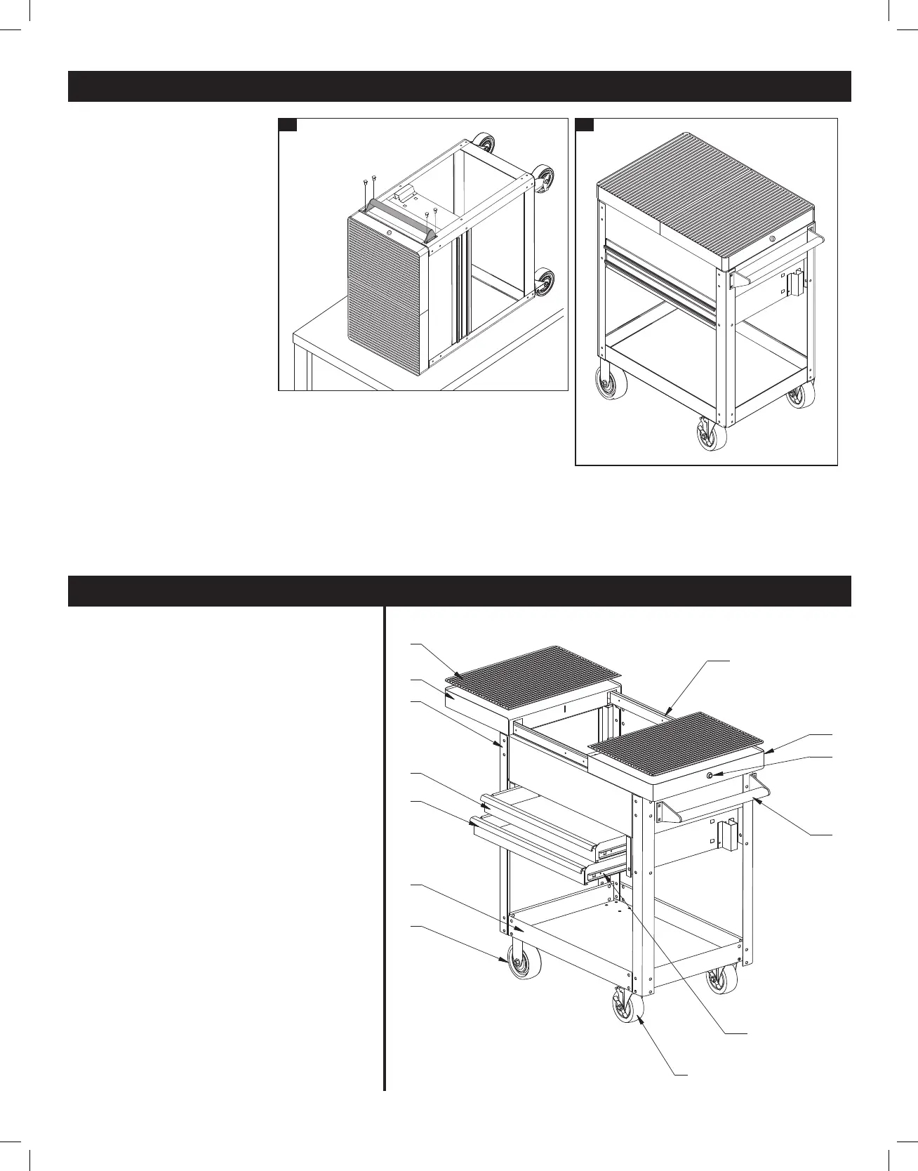
Step 5: Attaching the Handle
Attach the handle (#10) using
the 4 M8x20 handle bolts.
NOTE: The handle should be
assembled on the same side
as the locking casters (#8).
Step 6: The cart is complete.
ASSEMBLY INSTRUCTIONS
6.
5.
REPLACEMENT PARTS LIST
Item Part # Description # Req’d
1 RS8035RM Rubber mat 2
2 8035STBKN Sliding Top (black) 1
8035STRN Sliding Top (red)
3 8035STBK Sliding Top with Lock (black) 1
8035STR Sliding Top with Lock (red)
4 RS8035LGBK Leg/each (black) 4
RS8035LGR Leg/each (red)
5 8035DBK Drawer (black) 2
8035DR Drawer (red)
6 RS8035DH Drawer Handle 2
7 8035BTBK Bottom Tray (black) 1
8035BTR Bottom Tray (red)
8 RSFWH Fixed Wheel 2
9 RSSWLCS Locking Caster 2
10 RS8035SL Drawer Slides (pair) 2
11 RS8035PH Push Handle with Hardware 1
12 RS8035LK Lock with 2 Keys 1
13 RS8035SLT Sliding Top Slides (pair) 1
14 RS80354LK 4 Pc. Set EVA Liners (not shown) 1
15 RS8035CBK Caster Bolt Kit (not shown) 1
(set includes 16 M8 x 16 bolts,
32 washers and 16 M8 nuts)
16 RS8035LBK Leg Bolt Kit (not shown) 1
(set includes 32 M8 x 16 bolts
and 32 R8 washers)
1
2
4
5
6
7
8
13
12
3
11
10
9
8035_Manual_061311.indd 3 6/15/11 3:54 PM