User Manual 5 Electrical Installation
27
Gland Terminal
Step 1 Loosen the "INPUT DC+" union nut of gland terminals.
Step 2 Insert the “PV1+” cable through terminals of "INPUT DC+", and connect
the cable to the “PV1+” terminal inside the device. Enough wire bending
space should be ensured.
Cable (e.g. “PV1+”, “PV2+”… “PV1-”, “PV2-” etc.)
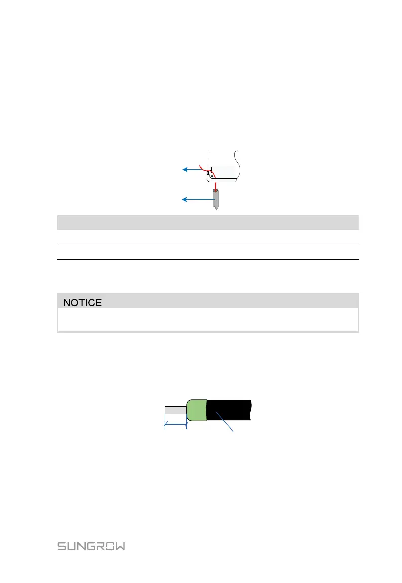
Step 3 Stripped off the cable insulation layer, using wire stripper, to reveal the
copper core, length as specified in above table.
Do not break the copper wire during stripping.
Step 4 Select proper terminal to the corresponding cable. For example,
E1612-XL, 16 stands for 16 mm
2,
the cross-sectional area of the
crimping cable; 12 stands for 12mm, the length of the crimping tube, see
the following figure.
Step 5 Crimp the cable. Insert the stripped cable into the terminal. Crimp the
cable using special tool (mouth of the crimping pliers should match the
cable cross section), see the following figure.
 Loading...