mPulse Power Box Installation Guide mPulse Power Box Installation Guide
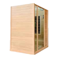
Step 7
Move along the front edge to the right front port of wires. Disconnect the 4-pin at G17 connector
(red, white, black, and blue wires) from the corresponding connection, F18. This wire’s connector
splits into two connections going out the other side, one labeled F5 and the other unused.
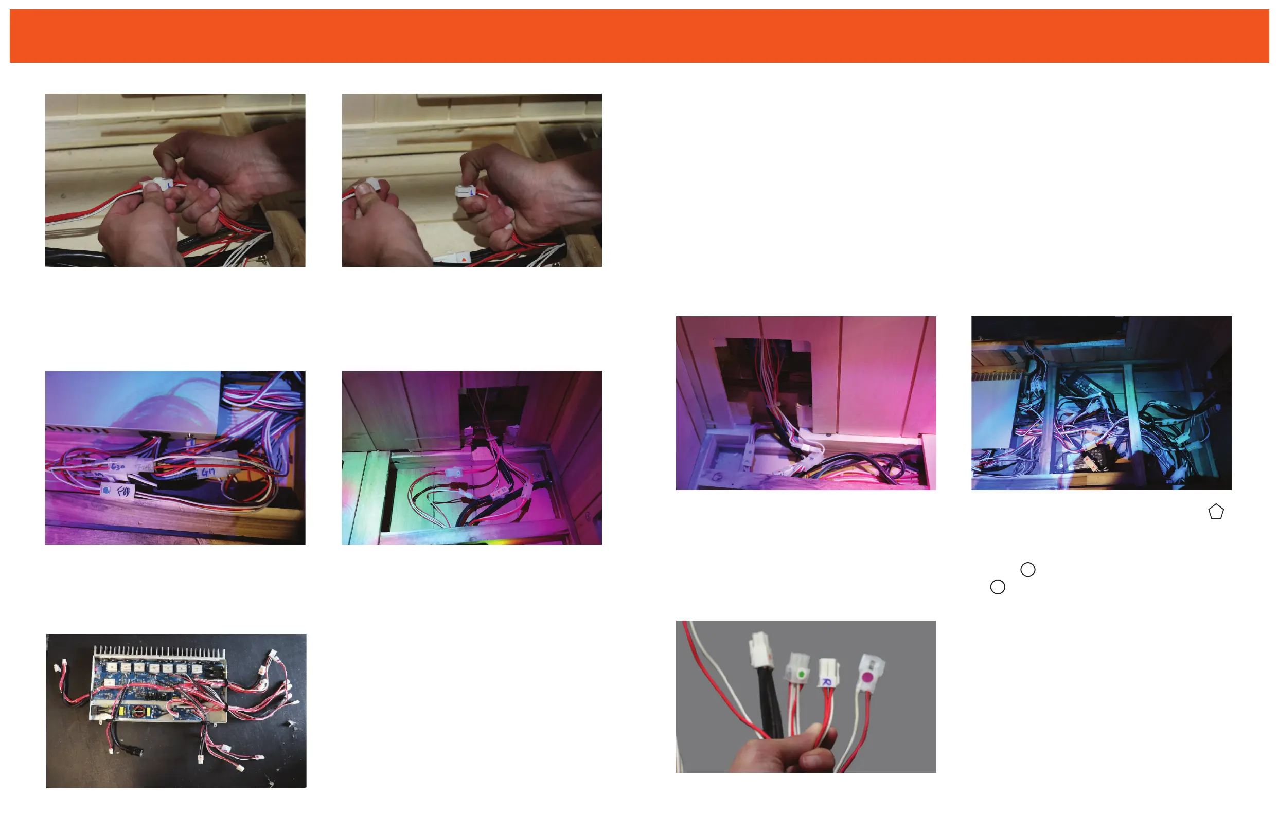
Disconnect the G4 power connector from the F7 power cables. Disconnect the G28 sensor line
from the corresponding F8 connector. You’ll nd a connector that is covered with black tape (red/
white wires) and zip-tied with a screw anchoring it to the base. Unscrew the anchored zip tie.
Step 8
Turn the corner to the rst port of wires on the right edge of the power box and note that these
wires pass through the wood support to the section to the immediate right of the power box in the
oor. There will be a zip tie holding a bundle of wires between the two black boxes. Cut this zip tie
and another in this section to the right, to allow for a better view of the connectors.
In this section, disconnect the G30 power connector from the corresponding F10 connector.
Disconnect the sensor connector (labeled R) from the corresponding connector F11.
Depending upon which mPulse sauna you have, you’ll nd this wire in one of the following
congurations: in Aspire, the F19 will split from the back wall to the left and right walls. In
Believe and Conquer, it will split from the right wall to the left wall. Discover and Empower
models may skip this step.
Now, disconnect the G32 NIR connector (semi-transparent connection) from the F19 harness.
Step 9
In this same section, disconnect the 3-pin G41 connector from the F16 harness.
Disconnect both the G42 and G43 2-pin connectors from the paired transformer
connectors (black box) located closer to the back wall.