8
1 Mounting kit (part # SQ-RMK5) is required per system.
1 System kit (part # SQ-SK) is required.
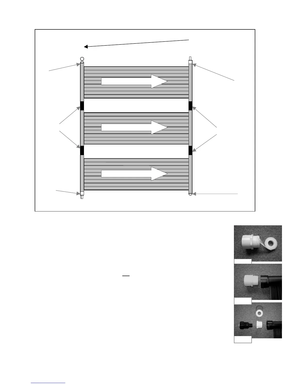
Diagram Step 3d
• Apply Teflon on one of the caps (SK-FTG-F). See Fig 3a-1.You only need 1 cap
for this type of installation.
• Thread the cap into the panels as per Diagram Step 3d. Do not over tighten.
See Fig 3a-2
• If you are using flexible piping to connect panels to your pump then Put "O" rings
(SK-FTG-I) on both combination adapters (SK-FTG-D) See Fig 3a-3. Thread both
combination adapters into the panels as per Diagram Step 3d. Do not over tighten.
See Fig 3a-4
OR
If you are using rigid piping to connect panels to your pump then apply Teflon on
both PVC adapters (SK-FTG-N). See Fig 3d-1. Thread both adapters into the
panels as per Diagram Step 3d. Do not over tighten. See Fig 3d-2.
• Apply Teflon on reducer adapter (SK-FTG-M) included in the system kit (SQ-SK) sold
separately. Thread reducer adapter into the panel as per diagram Step 3d.
Do not over tighten. See Fig 3d-3..
• Apply Teflon on vacuum relief valve (SK-VRV). Thread vacuum relief valve into
the reducer adapter. Do not over tighten. See Fig 3d-3.
Note: The vacuum valve assembly must be installed at the top of the panels as per diagram Step 3d.
3 d) Cont.
Vacuum Valve
3.75"
Outlet
3.75"
Inlet
Fig 3d-1
Fig 3d-3
A Minimum of 1 inch fall per 10 feet
Fig 3d-2